
Eureka
For R&D, Eureka makes reading and utilizing patents & technical documents easy.
Eureka AIR
Designed for self-driven R&D workflows. Generate viable solutions, solve complex R&D challenges, empower your innovation with AI.

Eureka Materials
Designed for material experts only. Revolutionize your material R&D, from search, analyze, to developing new materials.

TechResearch
Generate reliable direction feasibility study reports for your R&D in just a few steps.

TechSeek
Discover and master advanced knowledge NOW. Basics, ideas, possibilities, all at once.

TechMind
As an expert in R&D Theories, TechMind can generates customized viable solutions instantly.

TechRisk
Analyze your overall solution with one click, know your potential R&D risks in advance.

TechMonitor
Get weekly tech updates, stay abreast of the latest tech innovations and key insights.
Device used for polar plate cutting
A technology of pole plate and slide plate, applied in the direction of driving device, feeding device, large fixed members, etc., can solve the problems of lack of safety, affecting cutting thoroughness, and slow cutting speed, etc.
- Summary
- Abstract
- Description
- Claims
- Application Information
AI Technical Summary
Problems solved by technology
Method used
Image

Examples
Embodiment 1
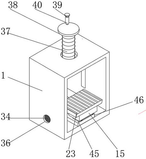
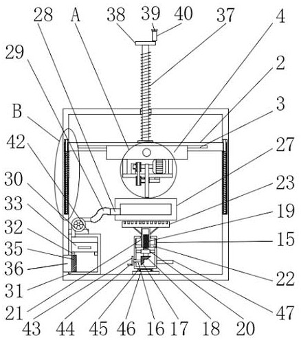
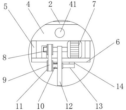
[0028] see Figure 1-6, the present invention provides a technical solution: a device for cutting polar plates, including a box body 1, the inner cavity of the box body 1 is provided with a slide bar 2, and the front and rear sides of the slide bar 2 are provided with chute 3 , the inner cavity of the chute 3 is slidably connected with a slide plate 4, and both sides of the bottom of the slide plate 4 are fixedly installed with a suspension rod 5, the bottom of the suspension rod 5 is fixedly installed with a bearing plate 6, and one side of the top of the load plate 6 is fixedly installed with a motor 7. The output shaft of the motor 7 is fixedly installed with a first transmission wheel 8, the surface of the first transmission wheel 8 is sleeved with a belt 9, the bottom bearing of the skateboard 4 is supported by a connecting rod 10, and one side of the connecting rod 10 is fixedly installed with a second Two transmission wheels 11, the first transmission wheel 8 is connect...
Embodiment 2
[0030] see Figure 1-6 The difference between this embodiment 2 and embodiment 1 is that a rotating rod 16 is provided at the bottom of one side of the gear case 15, and one side of the rotating rod 16 penetrates through the gear case 15 and extends to the inner cavity of the gear case 15. A gear 17, the top of the first gear 17 is meshed with a second gear 18, the top of the second gear 18 is fixedly installed with a first screw rod 19, the two sides of the inner cavity of the gear box 15 are fixedly installed with a fixed frame 20, the first screw rod 19 The top of the top runs through the fixed frame 20 and extends to the external thread of the fixed frame 20 to be connected with a screw sleeve 21, both sides of the top of the inner cavity of the gear box 15 are provided with notches, and both sides of the screw sleeve 21 bottom are fixedly installed with a limit rod 22 , the outer side of the limit rod 22 is slidably connected with the inner chamber of the notch, the top o...
PUM
 Abstract
Description
Claims
Application Information
 - R&D Engineer
- R&D Manager
- IP Professional
- Industry Leading Data Capabilities
- Powerful AI technology
- Patent DNA Extraction
Browse by: Latest US Patents, China's latest patents, Technical Efficacy Thesaurus, Application Domain, Technology Topic, Popular Technical Reports.
© 2024 PatSnap. All rights reserved.Legal|Privacy policy|Modern Slavery Act Transparency Statement|Sitemap|About US| Contact US: help@patsnap.com