Gypsum board cutting device for building suspended ceiling
A cutting device, gypsum board technology, applied in the direction of metal processing, etc., can solve the problems of slow consumption of physical strength, time-consuming and labor-intensive problems
- Summary
- Abstract
- Description
- Claims
- Application Information
AI Technical Summary
Problems solved by technology
Method used
Image
Examples
Embodiment 1
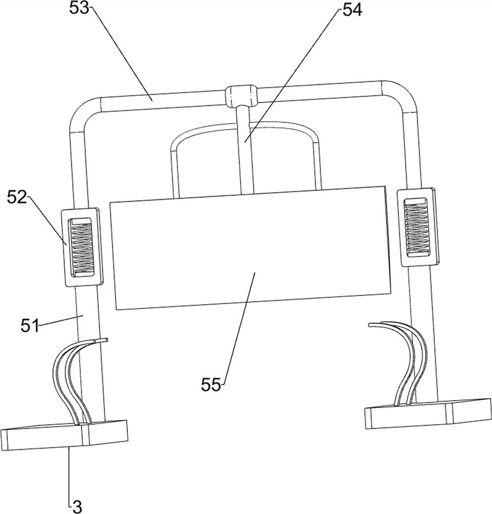
[0058] A kind of gypsum board cutting device for building suspended ceiling, such as figure 1 As shown, it includes a first fixed plate 1, a first support rod 2, a second fixed plate 3, a manual clamping mechanism 4 and a manual cutting mechanism 5, and a first support rod 2 is uniformly arranged on the right side of the first fixed plate 1. A second fixing plate 3 is provided between the tops of the first support bar 2 on the left side and the top of the first support bar 2 on the right side, and a manual clamping mechanism 4 is provided between the tops of the two second fixing plates 3 , A manual cutting mechanism 5 is provided between the top left sides of the two second fixing plates 3 , and the manual clamping mechanism 4 cooperates with the manual cutting mechanism 5 .
[0059] When people need to cut the gypsum board into pieces, they can use this kind of gypsum board cutting device for building suspended ceilings. First, people place a whole piece of gypsum board on t...
Embodiment 2
[0061] On the basis of Example 1, such as Figure 2-3 As shown, the manual clamping mechanism 4 includes a first discharge frame 41, a roller 42, a first connecting rod 43, a push rod 44, a first spring 45 and a clamping member 46, and the top of the two second fixing plates 3 There is a first discharge frame 41, and parallel rollers 42 are evenly arranged between the front and rear sides of the lower part of the first discharge frame 41, and the first connecting rods are symmetrically arranged on the outer upper wall of the left part of the two first discharge frames 41 43, a push rod 44 is slidably connected between the first connecting rod 43 and the first discharge frame 41, the push rod 44 is wound with a first spring 45, and the two ends of the first spring 45 are connected with the push rod 44 and the first discharge frame respectively. The outer wall of the material frame 41 is connected, and the inner end of the push rod 44 is provided with a clamping part 46 .
[00...
Embodiment 3
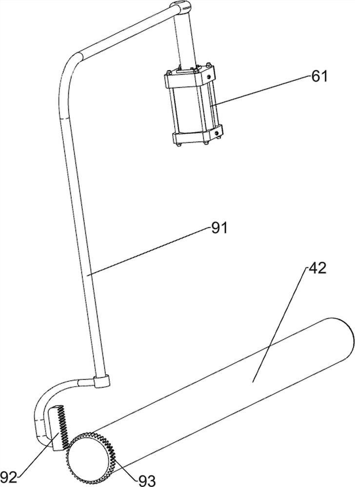
[0066] On the basis of Example 2, such as Figure 4-8 As shown, an automatic cutting mechanism 6 is also included, and the automatic cutting mechanism 6 includes a third fixed plate 61, a cylinder 62 and a third connecting rod 63, and a third fixed plate is connected between the upper right sides of the two first rods 51 61 , a cylinder 62 is installed on the top of the third fixing plate 61 , and a third connecting rod 63 is arranged on the top of the cylinder 62 , and the third connecting rod 63 is connected with the first telescopic member 53 .
[0067] Open the cylinder 62, the expansion and contraction of the output shaft of the cylinder 62 drives the third connecting rod 63 to reciprocate up and down, thereby driving the first telescopic part 53 to move up and down, realizing the effect of the cutter 55 automatically cutting the plasterboard, and closing the cylinder 62 to stop cutting.
[0068] Also includes an automatic clamping mechanism 7, the automatic clamping mech...
PUM
 Abstract
Description
Claims
Application Information
 - R&D
- Intellectual Property
- Life Sciences
- Materials
- Tech Scout
- Unparalleled Data Quality
- Higher Quality Content
- 60% Fewer Hallucinations
Browse by: Latest US Patents, China's latest patents, Technical Efficacy Thesaurus, Application Domain, Technology Topic, Popular Technical Reports.
© 2025 PatSnap. All rights reserved.Legal|Privacy policy|Modern Slavery Act Transparency Statement|Sitemap|About US| Contact US: help@patsnap.com


