Topology-number-adjustable vortex light beam generation device, system and method

A vortex beam and generating device technology, applied in the field of laser applications, can solve the problems of low utilization rate of light energy, high processing difficulty, difficulty and cost, etc., and achieve high energy conversion rate, good processing quality and high edge energy. Effect

Active Publication Date: 2021-03-23
武汉先河激光技术有限公司
View PDF4 Cites 6 Cited by
  • Summary
  • Abstract
  • Description
  • Claims
  • Application Information

AI Technical Summary

Problems solved by technology

Due to the high price of the phase plate, more phase plates are needed to realize the flexible and adjustable vortex optical topology number. This method is too expensive and not flexible enough.
2. Based on the axicon lens to generate a combined ring-shaped spot, but due to the limitations of the axicon lens material and processing technology, the range of taper that can be processed is limited at present. When the taper is too small, there will be a large error, and for crystal materials, more It is very difficult to process the mirror surface composed of different taper surfaces, so the ring-shaped light spot output by the transmission type axicon prism has a relatively small adjustable range in terms of ring radius and other parameters, and it is difficult to output multiple ring-shaped combined light spots. Larger, unable to flexibly meet different processing requirements. In addition, the material of the axicon mirror also affects the size of the optical power that can be tolerated; 3. Based on the computational holography method to generate a combined annular spot, the computational holography can in principle be designed to produce a composite annular spot Any spot including the spot, but because the computational holography needs to be completed by a spatial light modulator, the spatial light modulator generally uses off-axis first-order diffracted light, coupled with loss and other factors, so the utilization rate of light energy is low, and It cannot withstand kilowatt-level lasers, so it is relatively less used; 4. The laser with adjustable spot mode based on optical fiber is used to generate combined annular spot. This method realizes the difficulty and cost of adjusting the spot distribution mode in the optical fiber. , because there is no adjustable external optical path, it lacks in flexibility and convenience of use

Method used


Image

  • Topology-number-adjustable vortex light beam generation device, system and method
  • Topology-number-adjustable vortex light beam generation device, system and method
  • Topology-number-adjustable vortex light beam generation device, system and method

Examples


Embodiment 1

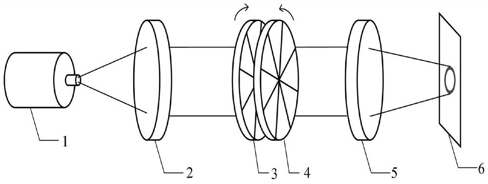
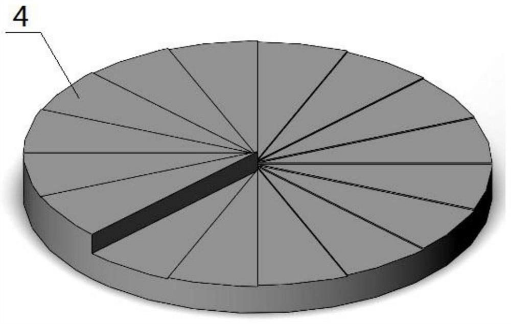
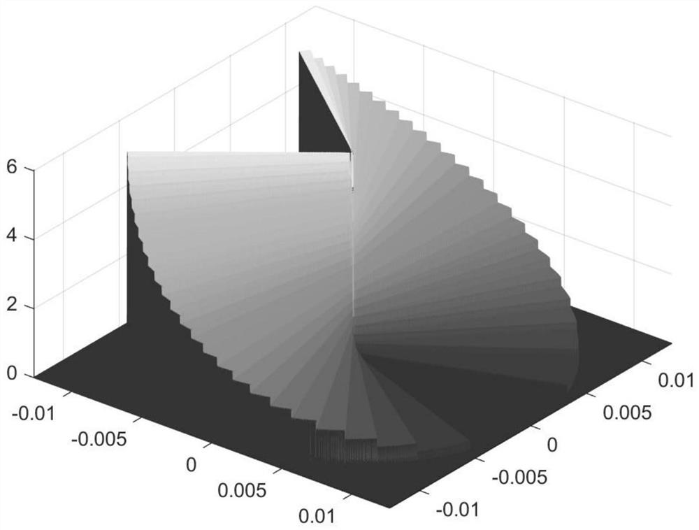
[0041] see figure 1 and figure 2 , this embodiment discloses a vortex beam generation device with adjustable topological number, including two helical-specific helical phase mirrors, and the phases of the two helical phase mirrors are respectively set to Aθ 2 and -Aθ 2 , A is a constant, which is used to control the variation range of the topological number of the obtained vortex beam. The topological number of the obtained vortex light takes all integers in the interval from 0 to 4Aπ, θ is the azimuth with the center of the spiral phase mirror as the origin, and two Two helical phase mirrors are arranged on the optical path in turn, and the laser beam is attached with a helical phase factor with a set topological number after passing through two helical phase mirrors in turn, turning into an annular vortex beam, which is controlled by rotating one or two helical phase mirrors. The angle difference between the two spiral phase mirrors is used to adjust the topological numbe...

Embodiment 2

[0051] see Figure 1 to Figure 7 , this embodiment discloses a vortex beam generation system with adjustable topological number, including a collimation unit 2, a focusing unit 5, and the vortex beam generation device described in Embodiment 1, and the vortex beam generation device is set at The optical path between the collimating unit 2 and the focusing unit 5;

[0052] The collimation unit 2 is used to collimate the input laser to obtain a collimated laser beam;

[0053] The vortex beam generating device is used to add a helical phase factor of the corresponding topological charge to the collimated laser beam emitted by the collimation unit to become an annular beam, and its topological charge is determined by the angle difference between the two helical phase mirrors ;

[0054] The focusing unit 5 is used to focus the ring-shaped beam emitted by the vortex beam generating device to obtain a light spot with ring-shaped energy distribution.

[0055] Further, before the co...

Embodiment 3

[0064] see Figure 8 , The vortex beam generation system of this embodiment also includes two scanning galvanometers, the two scanning galvanometers are arranged on the optical path between the vortex beam generating device and the focusing unit 5, and the optical path is carried out by two scanning galvanometers. Toggle to change the focus position of the focus plane. Other technical features of this embodiment are the same as those of Embodiment 2.

[0065] After the laser beam passes through the collimation unit 2 and the vortex beam generating device, it passes through the first scanning galvanometer 7, the second scanning galvanometer 9, and finally the focusing objective lens. , can change the focus position of the focal length surface, and perform fine laser processing such as marking, welding and cutting.

[0066] The light path of embodiment 3, the energy distribution of the light field on the focal plane is consistent with embodiment 1, because the ring-shaped ligh...


PUM


Abstract

The invention discloses a topology-number-adjustable vortex light beam generation device, system and method. The topology-number-adjustable vortex light beam generation device comprises two spiral phase mirrors, wherein the phases of the two spiral phase mirrors are respectively set as A[theta]2 and -A[theta]2, the two spiral phase mirrors are sequentially disposed on an optical path, and the topological number of the obtained vortex light beam is increased by 1 by increasing the angle difference of the two spiral phase mirrors. According to the invention, after passing through the device, a laser beam can be added with a spiral phase factor to realize phase modulation, so that the energy distribution of the laser beam is changed into annular distribution; the topological number of the obtained vortex beam is adjusted by rotating one or two spiral phase mirrors to control the angle difference of the two spiral phase mirrors so as to realize an annular light spot with an adjustable size; and a group of spiral phase mirrors with second-order nonlinear spiral structures are designed and superposed to generate vortex light beams with adjustable topological numbers, so that annular light spots with concentrated energy distribution at the edge, larger diameter, longer focal depth and adjustable size are formed.

Description

technical field [0001] The invention belongs to the field of laser applications, and more specifically, the invention relates to a vortex beam generation device, system and method with adjustable topology number. Background technique [0002] The energy distribution of ordinary Gaussian beams decreases from the center to the edge, and most of the energy is concentrated in the central area. In the field of laser processing, especially in the fields of laser welding, cutting, cladding, etc., ablation and other phenomena may occur if the center energy is too high, and due to insufficient energy at the edge, when performing deep processing such as laser cutting, the deeper the processing depth, the edge The energy is even more insufficient, which leads to uneven cutting section, which significantly limits the processing quality and processing accuracy. [0003] In view of the above problems, the commonly used treatment method is to change the Gaussian distribution of light spot...

Claims


Application Information

Patent Timeline
Patent Type & Authority Applications(China)
IPC IPC(8): G02B26/06G02B27/09G02B26/10
CPCG02B26/06G02B26/105G02B27/0927G02B27/0944
Inventor 张兰天秦应雄徐家明段光前
Owner 武汉先河激光技术有限公司
Why Eureka
Try Eureka