Lifting device for drilling pump

A technology for lifting devices and drilling pumps, applied in the direction of lifting devices, fluid pressure actuating devices, lifting frames, etc., can solve the problems of unloading and inability to load drilling pumps, and achieve the effect of reducing lifting costs

Active Publication Date: 2021-03-26
中油国家油气钻井装备工程技术研究中心有限公司 +2
View PDF5 Cites 0 Cited by
  • Summary
  • Abstract
  • Description
  • Claims
  • Application Information

AI Technical Summary

Problems solved by technology

[0003] The purpose of the present invention is to provide a lifting device for drilling pumps, which solves the problem in the prior art that the drilling pump cannot be loaded onto or unloaded from the transport vehicle without a crane

Method used


Image

  • Lifting device for drilling pump
  • Lifting device for drilling pump
  • Lifting device for drilling pump

Examples


Embodiment Construction

[0028] The present invention will be described in detail below in conjunction with the accompanying drawings and specific embodiments.

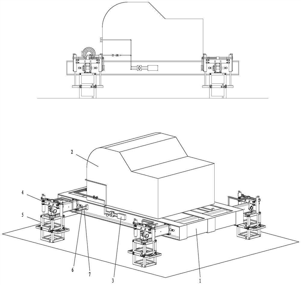
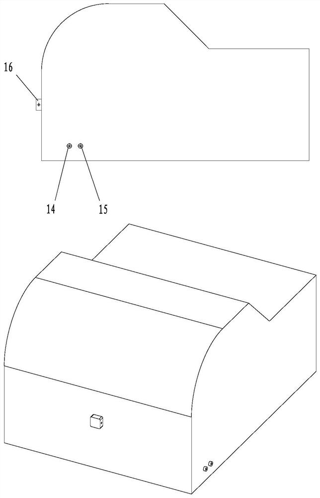
[0029] A lifting device for a drilling pump, the structure of which is as follows: Figure 1 to Figure 11 shown. The lifting device is mainly composed of a base assembly 1, a drilling pump 2, an oil circuit assembly 3, a lifting frame assembly 4, a support frame assembly 5, oil pipes 6, and oil pipes 7. The working principle of the lifting device is as follows: Figure 12 to Figure 18 shown.

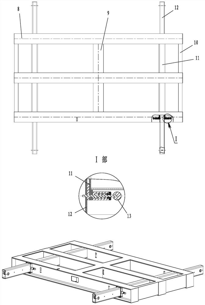
[0030] The structure of the base assembly is as figure 2 As shown, it is composed of a main beam 8, a cross beam 9, a sealing plate 10, a fixed beam 11, a traveling beam 12, and a positioner 13. The upper part of the base assembly is used to install the drilling pump 2 and the oil circuit assembly 3. The base assembly passes through The hoisting hole at the end of the traveling beam is connected with the lifting frame assembly 4. The main beams, c...


PUM


Abstract

The invention discloses a lifting device for a drilling pump. The lifting device for the drilling pump comprises a base assembly, wherein the drilling pump and an oil way assembly are arranged on theupper part of the base assembly; the base assembly is connected with a lifting frame assembly through a lifting hole in the end of a moving beam; and a supporting frame assembly is arranged below themoving beam. According to the device, the lifting frame assembly is adopted to lift the drilling pump, the stacked supporting frame assembly is adopted to provide support for the drilling pump, the function of lifting the drilling pump to the required height from the ground is achieved through mutual cooperation and coordinated action, and meanwhile, the device also has the function of lowering the drilling pump to the ground from a certain height, so that the drilling pump can be loaded on or unloaded from a transport vehicle by utilizing the device under the condition of no crane. The oil way assembly is integrated in the base, the external space of the drilling pump is not occupied, the device is simple in structure and easy to implement, and the lifting cost of the drilling pump is saved.

Description

technical field [0001] The invention belongs to the technical field of oil and gas exploration and development equipment, and relates to a lifting device for a drilling pump. Background technique [0002] When a major failure occurs to the drilling pump at the drilling site, it is necessary to load the drilling pump on a transport vehicle and transport it to a professional repair shop for overhaul. At present, the method of lifting the drilling pump by crane is generally used to load the drilling pump on the transport vehicle. This method is simple and fast, but there are also some problems. One is that the drilling pump is heavy and requires a large-tonnage crane to complete the lifting operation. The second is that the drilling operation sites are mostly located in remote areas far from the city, and it takes a long time for the crane to rush to the operation site from the city for a long distance. The third is that when the crane arrives at the operation site, it only c...

Claims


Application Information

Patent Timeline
Patent Type & Authority Applications(China)
IPC IPC(8): B66F7/20B66F7/28F15B13/02F15B13/06
CPCB66F7/20B66F7/28F15B13/02F15B13/06
Inventor 杜向阳郝建旭曾兴昌周小明廖刚胡楠颜岁娜
Owner 中油国家油气钻井装备工程技术研究中心有限公司
Why Eureka
Try Eureka