Natural resource monitoring device

A technology for monitoring devices and natural resources, applied in measuring devices, mechanical measuring devices, using mechanical devices, etc., can solve problems such as large errors, inaccurate adjustment, and different adjustment positions.

Pending Publication Date: 2021-04-02
CHONGQING VOCATIONAL INST OF ENG
View PDF7 Cites 0 Cited by
  • Summary
  • Abstract
  • Description
  • Claims
  • Application Information

AI Technical Summary

Problems solved by technology

[0003] In the process of monitoring natural resources in the prior art, the monitoring equipment needs to be placed in a fixed position. However, the position of the monitor cannot be adjusted in the existing monitoring equipment, or although the position of the monitor can be adjusted, the adjustment process is complicated , and the adjustment is not precise, the position of each adjustment is different, resulting in a large error

Method used


Image

  • Natural resource monitoring device
  • Natural resource monitoring device
  • Natural resource monitoring device

Examples


Embodiment 1

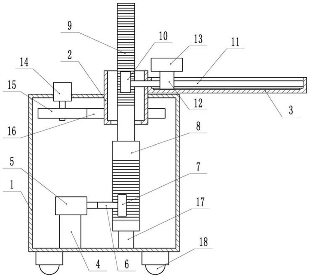
[0030]Embodiments are basicallyfigure 1 As shown: a natural resource monitoring device, including the mounting tank 1 and the monitor 13, the inside of the mount 1, the top end of the mounting tank 1 is connected, the support box 2 is hollow, and the top and bottom ends of the support box 2 Both are open ends, the support box 2 in the present embodiment passes through the top end of the mounting tank 1 and rotates through a bearing with the mounting tank 1.

[0031]One side of the support box 2 is fixedly connected to the connecting plate 3, and the connecting plate 3 is located above the mounting tank 1, and the connecting plate 3 is welded to the support box 2. A groove is opened on the connecting plate 3, and a screw 11 is provided in the connecting plate 3, and the screw 11 is located in the recess, and one end of the screw 11 extends into the support box 2 and has a first gear 10 by a flat key. The other end of the screw 11 and the right side wall of the connecting plate 3 rotates...

Embodiment 2

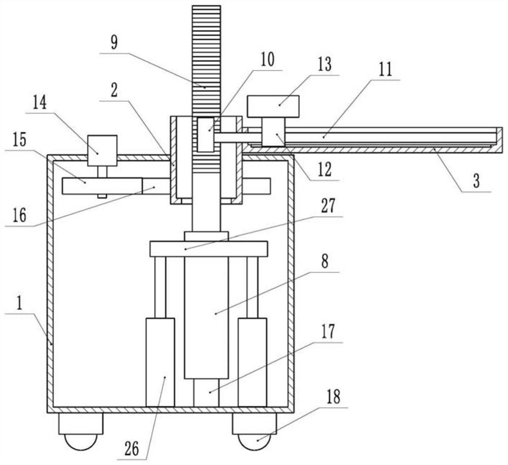
[0041]Such asimage 3 As shown, a natural resource monitoring device, the difference from the embodiment is that the surface of the drive column 8 is smooth, and the surface is not set, and the drive unit includes a cylinder 26 and a branch plate 27, a sheet plate 27 and a drive. The column 8 is rotatably connected by a bearing coaxial, and the output shaft of the cylinder 26 is fixed to the bolt 27, and the cylinder 26 is fixed by the bottom of the cylinder 1 through the bolt.

[0042]When used, the drive column 8 is vertically adjusted by the telescopic movement of the output shaft of the cylinder 26, thereby achieving adjustment of the linear position of the monitor 13, and when the angle of the monitor 13 is required, through the first motor 14 When driving the active gear 15 and the driven gear 16 rotate while driving the support box 2, the drive column 8 can be rotated between the brackets 27, thereby adapting to the support box 2. Turn, in turn, the angular position adjustment of...

Embodiment 3

[0044]Such asFigure 4 As shown, a natural resource monitoring device, the difference from the embodiment is also provided with adjustment block 22 in the connecting plate 3, and the monitor 13 is located on the adjustment block 22 and is fixed to the adjustment block 22 through a bolt. The adjustment block 22 is slidably fitted with the side wall of the connecting plate 3, and in the present embodiment, the slip groove 21 is opened on both sides of the groove of the connecting plate 3, and the front and rear ends of the adjustment block 22 are welded. Block, two bumps are inserted into two slip grooves 21 and slide together with the slip groove 21, so that the adjustment block 22 is a sliding cooperation relationship between the connecting plate 3. In this embodiment, the tip end of the adjustment block 22 is parallel to the top end of the connecting plate 3.

[0045]The natural resource monitoring apparatus in this embodiment further includes an adjustment lever 23, and the adjustment...


PUM


Abstract

The invention relates to the field of monitoring equipment, and discloses a natural resource monitoring device. The natural resource monitoring device comprises a mounting box and a monitor, a supporting box is connected to the top end of the mounting box, a connecting plate is fixedly connected to one side of the supporting box, a groove is formed in the connecting plate, a lead screw is arrangedin the connecting plate, one end of the lead screw extends into the supporting box and is fixedly connected with a first gear, the other end of the lead screw is rotationally connected with the sidewall of the connecting plate, the lead screw is in threaded fit with a sliding block, the sliding block is in sliding connection with a groove of the connecting plate, the monitor is connected with the sliding block, a driving column and a rack are arranged in the mounting box, the rack is located at the top end of the driving column and fixedly connected with the driving column, the driving column can vertically slide, the rack penetrates through the supporting box and is in vertical sliding fit with the supporting box, the first gear meshes with the rack, and a driving unit for driving the driving column to do vertical reciprocating motion is arranged in the mounting box. According to the natural resource monitoring device, the position of the monitor can be adjusted, and the use is moreflexible and convenient.

Description

Technical field[0001]The present invention relates to the field of monitoring equipment, and more particularly to a natural resource monitoring device.Background technique[0002]At present, in order to protect natural resources, understand the natural resources, the relevant departments need to monitor natural resources to achieve the purpose of ensuring the use of natural resources.[0003]In the prior art, the monitoring device is placed in a fixed position in the process of monitoring the natural resources, but due to the existing monitoring equipment, the position of the monitor can be adjusted, although the position of the monitor can be adjusted, the adjustment process is complex. And the adjustment is not accurate, and the position of each adjustment is not larger.Inventive content[0004]The present invention provides a natural resource monitoring device, which is intended to adjust the position of the monitor.[0005]In order to achieve the above object, the present invention adop...

Claims


Application Information

Patent Timeline
Patent Type & Authority Applications(China)
IPC IPC(8): F16M11/42F16M11/08F16M11/18G01B3/04G01B5/04
CPCF16M11/42F16M11/043F16M11/08F16M11/18G01B3/04G01B5/043
Inventor 高彩霞
Owner CHONGQING VOCATIONAL INST OF ENG
Why Eureka
Try Eureka