A booster-type drainage gas production device for the "snake-curved" horizontal section of a horizontal well

A technology for water drainage and gas recovery and horizontal section, which is applied in the direction of mining fluid, earthwork drilling, wellbore/well components, etc., and can solve the problem of blocked gas flow channels, drainage and gas recovery technology that is difficult to lower into the horizontal section, drainage and gas recovery devices and Less research on tools and other issues can achieve the effect of accelerating the discharge rate, improving the efficiency of drainage and gas recovery, and ensuring normal production capacity

Active Publication Date: 2022-03-22
CHONGQING UNIVERSITY OF SCIENCE AND TECHNOLOGY
View PDF0 Cites 0 Cited by
  • Summary
  • Abstract
  • Description
  • Claims
  • Application Information

AI Technical Summary

Problems solved by technology

During the gas well production process, when the bottom of the well begins to produce water, due to the difference in gas-liquid density, gas-liquid separation will occur in the horizontal section, the gas flows in the upper part of the pipeline, and the gas flows in the lower part of the pipeline. The curved structure often causes liquid accumulation in the low-lying places of the "sag", which blocks the gas flow channel, affects the normal production of the gas well, and reduces the efficiency of the gas well
[0003] At present, drainage gas recovery technologies mainly include foam drainage gas recovery, plunger soaked water gas recovery, optimized pipe string drainage gas recovery, and machine-pumped drainage gas recovery. There are few researches on the drainage and gas recovery devices and tools of the low-lying liquid accumulation wells in the "snake" type horizontal section. At present, it is still in the blank period of technology

Method used


Image

  • A booster-type drainage gas production device for the "snake-curved" horizontal section of a horizontal well
  • A booster-type drainage gas production device for the "snake-curved" horizontal section of a horizontal well
  • A booster-type drainage gas production device for the "snake-curved" horizontal section of a horizontal well

Examples


Embodiment Construction

[0033] The present invention will be further described below in conjunction with embodiment and accompanying drawing.

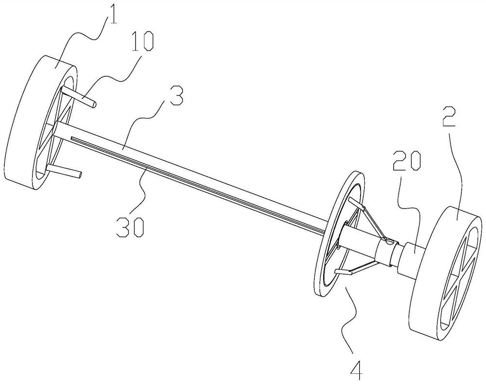
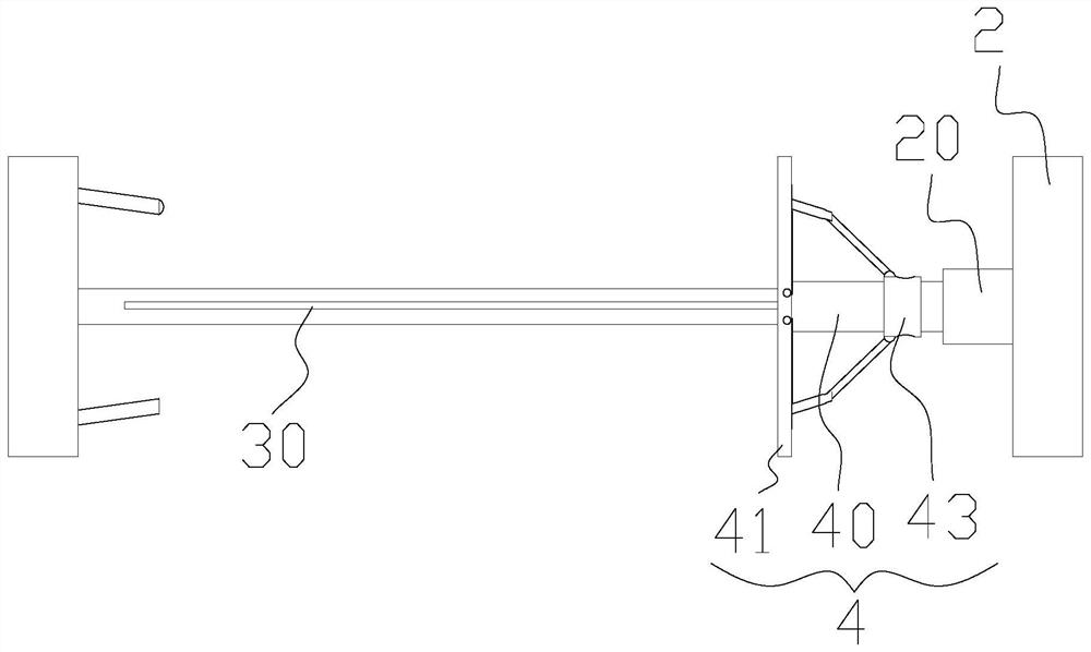
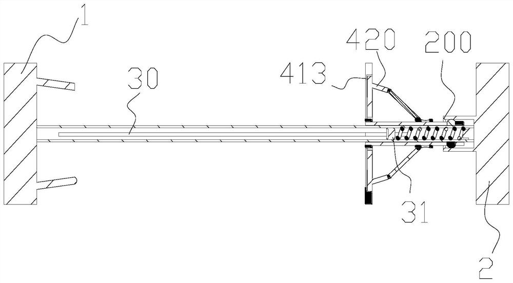
[0034] refer to Figure 1 to Figure 9 A booster drainage and gas recovery device for the "serpentine" horizontal section of a horizontal well as shown, includes a front fixing seat 1 and a rear fixing seat 2 facing each other, and the two ends are connected with the front fixing seat 1 and the rear fixing seat 2 respectively. The installation shaft 3 connected to the thick fixed seat 2 (the front, back, left and right, and up and down directions in this application are all based on the position in the horizontal section during use as a reference, and the back is close to the bottom of the well, the front is close to the wellhead, and the bottom is close to the lower side wall of the wellbore. , the upper side wall is the upper), as shown in the figure, the main structures of the front fixing seat 1 and the rear fixing seat 2 in this embodiment are consistent,...


PUM


Abstract

The invention discloses a booster drainage and gas production device suitable for the "serpentine" horizontal section of a horizontal well. They are respectively fixedly connected with the front fixing seat and the rear fixing seat. The front fixing seat and the rear fixing seat are both disc-shaped, and are provided with holes for the fluid to flow along its axial direction; A booster, which can make the channels on the front and rear fixing seats in a connected state when approaching the front fixing seat, and block the channels on the front and rear fixing seats when approaching the rear fixing seat to help A reset mechanism is arranged between the push piece and the rear fixing seat. The patent of the invention makes full use of the production air pressure to push forward the liquid accumulation in the low-lying areas of the horizontal section, prevent the production of gas wells from being affected by the liquid accumulation in the low-lying areas of the horizontal section, accelerate the liquid discharge rate, improve the efficiency of drainage and gas recovery, and ensure normal production capacity.

Description

technical field [0001] The invention belongs to drainage and gas recovery devices for gas production wells in oil and gas fields, and in particular relates to a boosting drainage and gas recovery device for the "snake" horizontal section of a horizontal well. Background technique [0002] During the production of gas wells, liquid accumulation or water production may occur in the wellbore of the gas well and the formation near the bottom of the well, which will affect the normal production of the gas well. Horizontal wells are currently an important well type for natural gas exploitation. Due to the influence of geological conditions and drilling technology, it is difficult to ensure that the horizontal section is in a straight state during the drilling process of horizontal wells, and "snake" type horizontal sections often appear. , its horizontal section presents an up-and-down undulating structure in the longitudinal direction, and a "concave" structure and a "convex" str...

Claims


Application Information

Patent Timeline
Patent Type & Authority Patents(China)
IPC IPC(8): E21B43/00
CPCE21B43/00
Inventor 石书强戚志林严文德黄小亮张旭李继强方飞飞袁迎中李俊莫非王琦董明达王杰
Owner CHONGQING UNIVERSITY OF SCIENCE AND TECHNOLOGY
Why Eureka
Try Eureka