Power electrical transformer convenient to install

A technology for electric power and transformers, applied in the field of transformers, can solve problems such as the difficulty of fixing the inside of the box, the small space between the transformer and the box, and the increased cost.

Pending Publication Date: 2020-10-30
戴炳泉
View PDF5 Cites 3 Cited by
  • Summary
  • Abstract
  • Description
  • Claims
  • Application Information

AI Technical Summary

Problems solved by technology

Since the box-type transformer installs the transformer inside the box, in order to reduce the volume, the box is often designed as small as possible, resulting in a small space between the transformer and the box, so that when the transformer is installed inside the box, the Fixing inside the box is often very difficult
The existing general method is to fix the transformer on the base first, then put the shell on the outside of the transformer, and then fix the shell on the base, but when the transformer breaks down and needs to be repaired, the maintenance personnel can only repair the front side of the transformer. The rear side cannot be approached due to the obstruction of the shell, so the shell can only be removed, and the work efficiency is greatly reduced. The shell is often damaged during the removal process, resulting in waste of resources and increased costs

Method used


Image

  • Power electrical transformer convenient to install
  • Power electrical transformer convenient to install
  • Power electrical transformer convenient to install

Examples


Embodiment Construction

[0033] Example embodiments will now be described more fully with reference to the accompanying drawings. Example embodiments may, however, be embodied in many forms and should not be construed as limited to the examples set forth herein; Fully conveyed to those skilled in the art. The drawings are merely schematic illustrations of the present disclosure and are not necessarily drawn to scale. The same reference numerals in the drawings denote the same or similar parts, and thus repeated descriptions thereof will be omitted.

[0034] Furthermore, the described features, structures, or characteristics may be combined in any suitable manner in one or more example embodiments. In the following description, numerous specific details are provided in order to give a thorough understanding of example embodiments of the present disclosure. However, those skilled in the art will appreciate that the technical solutions of the present disclosure may be practiced without one or more of ...


PUM


Abstract

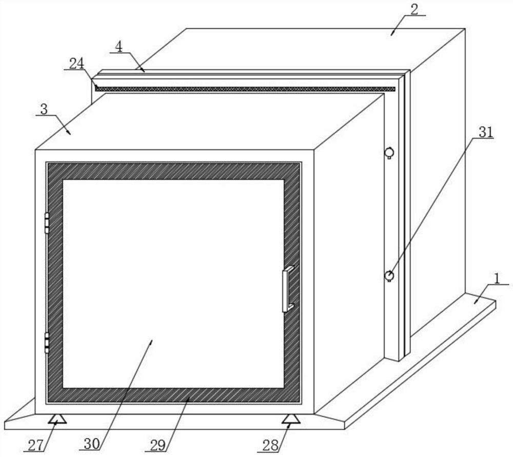
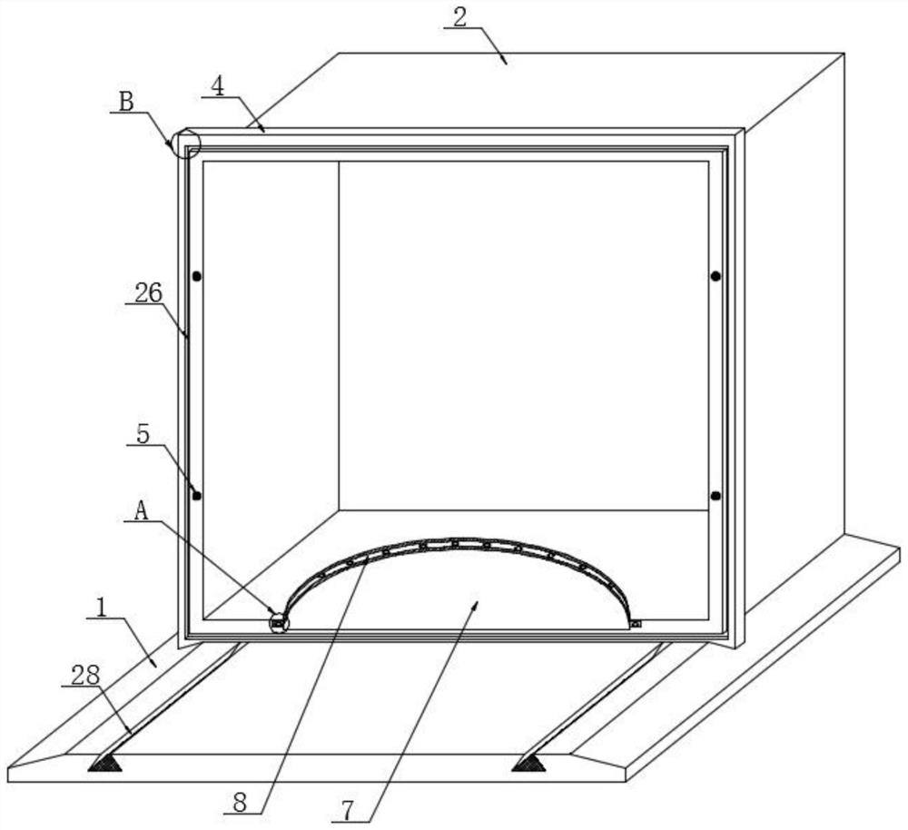
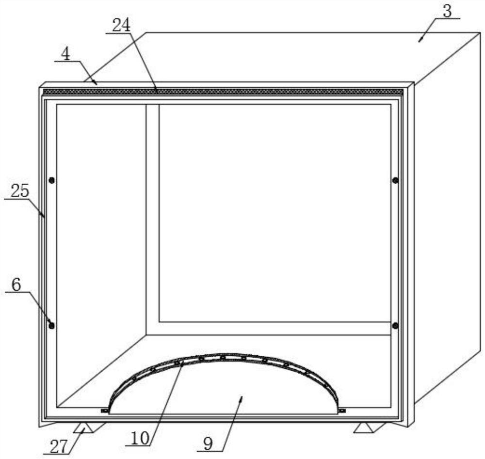
The invention discloses a power electrical transformer convenient to install. Specifically, the invention relates to the technical field of transformers, the transformer comprises a base plate, a front shell and a rear shell are arranged at the top of the base plate, the bottom end face of the rear shell is fixedly connected with the top end face of the base plate, the bottom end face of the frontshell is movably connected with the top end face of the base plate, a sealing door is hinged to the end face, away from the rear shell, of the front shell through hinges, and an installation and maintenance mechanism is arranged between the front shell. According to the invention, the first caulking groove and the second caulking groove form a circular caulking groove to limit the bottom end of the rotating disc; when the transformer main body needs to be maintained, the buckling block at the bottom of one end of the transverse plate is separated from the buckling groove in the rotating discso as to unlock the rotating disc, and the buckling block at the bottom of one end of the transverse plate is separated from the buckling groove in the rotating disc so as to unlock the rotating disc,so that the peripheral side surface of the transformer main body is convenient to maintain in all directions, and the front shell and the rear shell are disassembled when the transformer main body needs to be replaced.

Description

technical field [0001] The invention relates to the technical field of transformers, more specifically, the invention relates to a power electrical transformer that is easy to install. Background technique [0002] A transformer is a static electrical device that is used to change an AC voltage (current) of a certain value into another voltage (current) with the same frequency or several different values. It is based on the principle of electromagnetic induction The main components to realize the transmission of electric energy are the primary coil, the secondary coil and the iron core (magnetic core). Transformers can be divided into power transformers, test transformers, instrument transformers and special-purpose transformers according to their uses. Among them, power transformers are necessary equipment for power transmission and distribution and power user distribution; test transformers can withstand voltage (liter voltage) test equipment; instrument transformers are ...

Claims


Application Information

Patent Timeline
Patent Type & Authority Applications(China)
IPC IPC(8): H01F27/02
CPCH01F27/02H01F27/022
Inventor 不公告发明人
Owner 戴炳泉
Why Eureka
Try Eureka