
Optical imaging lens

An optical imaging lens and imaging technology, applied in the field of optical components, can solve the problems of increased design difficulty and increased design difficulty, and achieve the effects of reducing the aperture value, increasing the image height, and improving the resolution

Active Publication Date: 2021-04-06
GENIUS ELECTRONICS OPTICAL XIAMEN
View PDF3 Cites 2 Cited by
  • Summary
  • Abstract
  • Description
  • Claims
  • Application Information

AI Technical Summary

Problems solved by technology

However, the design of large aperture allows the lens to accept more imaging light, making the design more difficult; while the high resolution increases the resolution of the lens, and the design of large aperture makes the design more difficult.

Method used


Image

  • Optical imaging lens
  • Optical imaging lens
  • Optical imaging lens

Examples


Embodiment Construction

[0111] The terms "optical axis area", "circumferential area", "concave" and "convex" used in this specification and claims should be interpreted based on the definitions listed in this specification.

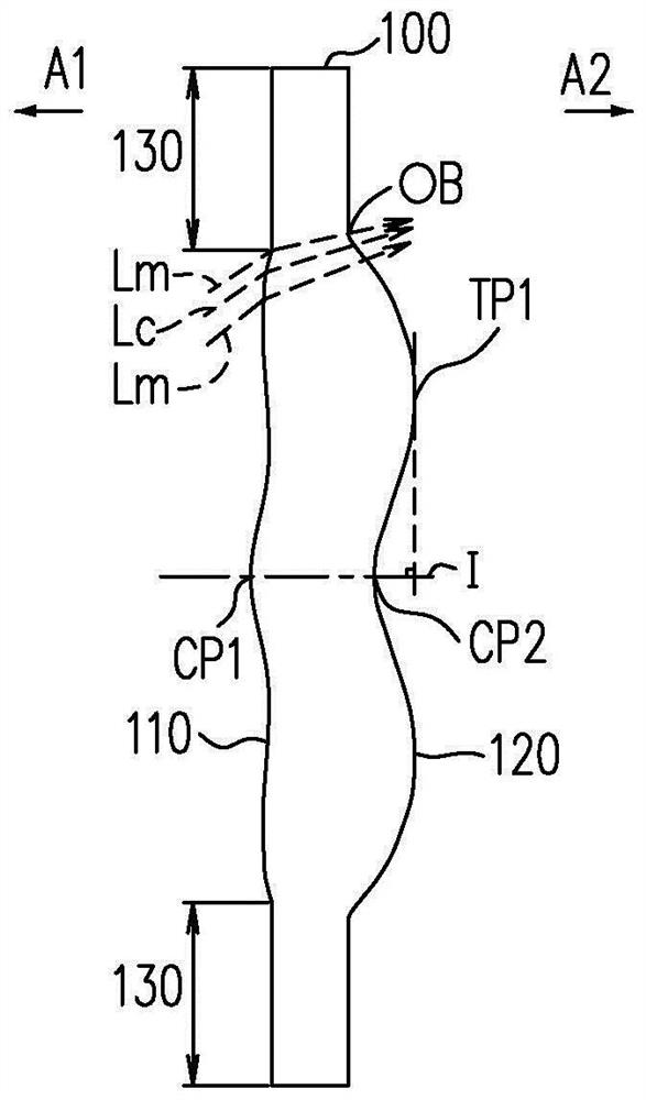
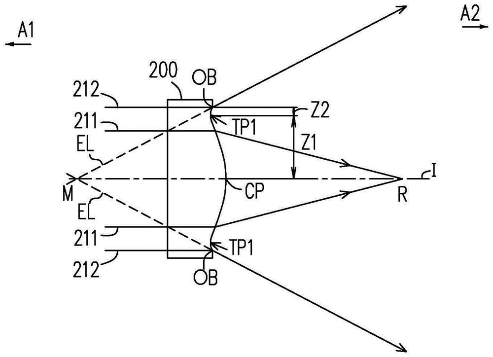
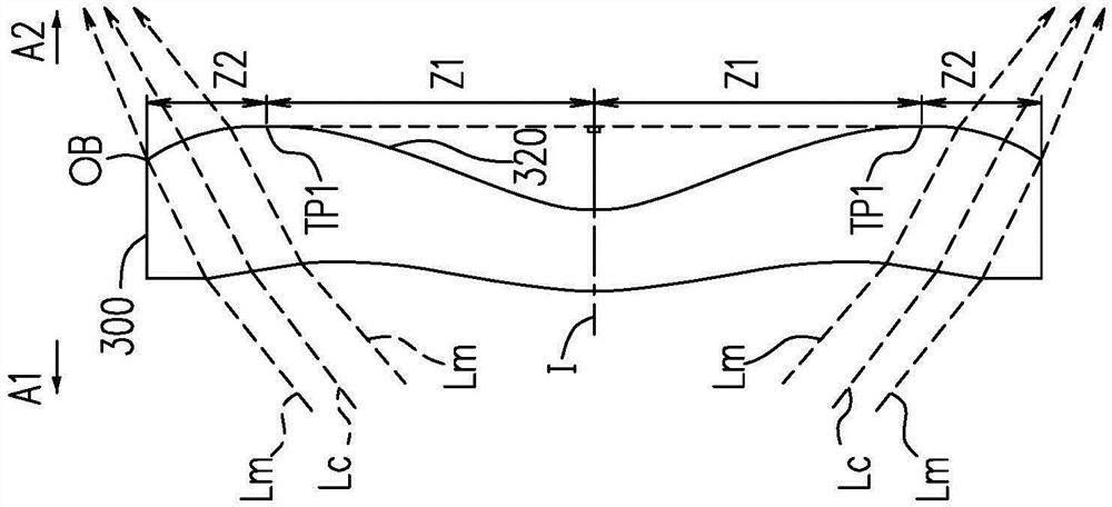
[0112] The optical system of the present specification includes at least one lens, which receives the imaging light from the incident optical system parallel to the optical axis to within an angle of half field of view (HFOV) relative to the optical axis. The imaging light is imaged on the imaging plane through the optical system. The term "a lens has a positive refractive power (or negative refractive power)" means that the paraxial refractive power of the lens calculated by Gaussian optical theory is positive (or negative). The so-called "object side (or image side) of the lens" is defined as a specific range where imaging light passes through the lens surface. Imaging rays include at least two types of rays: chief ray (chief ray) Lc and marginal ray (marginal ray) Lm (such a...


PUM


Abstract

The invention relates to an optical imaging lens, which sequentially comprises a first lens, a second lens, a third lens, a fourth lens, a fifth lens, a sixth lens, a seventh lens, an eighth lens and a ninth lens from an object side to an image side along an optical axis, wherein each of the first to ninth lenses comprises an object side surface facing the object side and allowing imaging light to pass through and an image side surface facing the image side and allowing imaging light to pass through, the first lens has a positive refractive index, the circumferential area of the image side surface of the first lens is a concave surface, the optical axis area of the object side surface of the second lens is a convex surface, the optical axis area of the image side surface of the ninth lens is a concave surface, only nine lenses of the optical imaging lens are provided, and the following conditional expressions are satisfied: V1 + V2 is less than or equal to 80.000 and V3 + V7 is more than or equal to 50.000.

Description

technical field [0001] The invention relates to an optical component, and in particular to an optical imaging lens. Background technique [0002] The specifications of portable electronic devices are changing with each passing day, and their key components - optical imaging lenses are also becoming more diversified. For the main lens of the portable electronic device, not only a larger aperture and a shorter system length are required, but also higher pixels and higher resolution are pursued. The high pixel size implies that the image height of the lens must be increased, and the pixel requirement is increased by using a larger image sensor to receive imaging light. However, the large aperture design allows the lens to accept more imaging light, which makes the design more difficult; and the high resolution increases the resolution of the lens, and the large aperture design makes the design more difficult. Therefore, how to add multiple lenses to the limited system length ...

Claims


Application Information

Patent Timeline
Patent Type & Authority Applications(China)
IPC IPC(8): G02B13/00G02B13/18
CPCG02B13/0015G02B13/0045G02B13/18G02B9/64G02B3/04
Inventor 赖永枫林茂宗张加欣
Owner GENIUS ELECTRONICS OPTICAL XIAMEN
Learn More