Gas fuel storage device for vehicle

A gaseous fuel and storage device technology, applied in gas/liquid distribution and storage, container structure installation device, power device, etc., can solve the problems of narrowed trunk or rear seat space, reduced internal marketability, etc.

Pending Publication Date: 2021-04-09
HYUNDAI MOTOR CO LTD +1
0 Cites 0 Cited by

AI-Extracted Technical Summary

Problems solved by technology

When the gas container is used, since the supporting body is mounted on the vehicle body, the space ...

Method used

[0032] The gas containers 2 may be accommodated in a plurality of storage spaces 33 one by one. The gas container 2 inserted into the storage space 33 may be connected to a first diaphragm portion adjacent to the gas container 2 among the plurality of first diaphragm portions 31 and a portion adjacent to the gas container 2 among the plurality of second diaphragm portions 32 . The second diaphragm is partially supported while being in contact. Therefore, even when running, the flow of the gas container 2 can be minimized.
[0042] In the gas fuel storage device constructed as described above, since the case 1 can be mounted on the lower side of the vehicle body 6, the gas storage capacity can be secured more easily than the conventional gas container, and the inner space of the vehicle body 6 is not limited. It is necessary to provide the supporting body with the existing large gas container i...

Abstract

A gas fuel storage device for a vehicle is provided. The device more easily secures a gas fuel storage capacity and prevents interior marketability of the vehicle from deteriorating.

Application Domain

Vessel mounting detailsFuel supply apparatus +6

Technology Topic

Automotive engineeringMechanical engineering +2

Image

  • Gas fuel storage device for vehicle
  • Gas fuel storage device for vehicle
  • Gas fuel storage device for vehicle

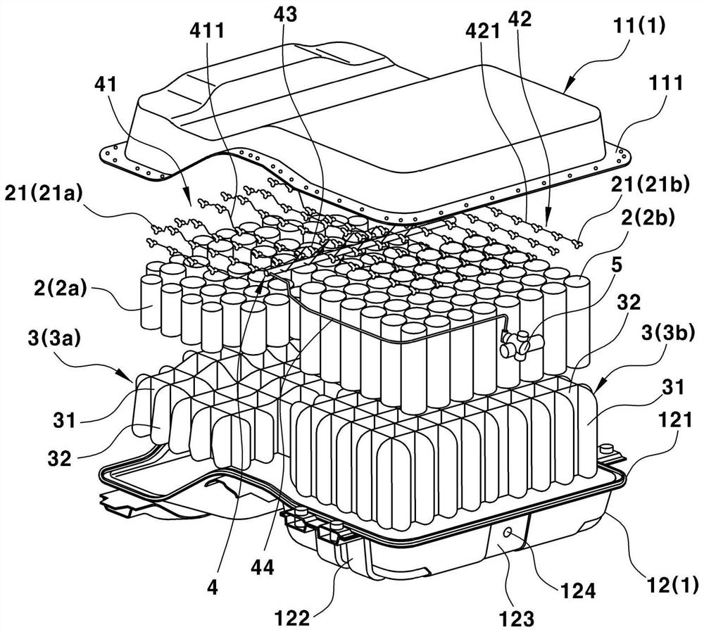
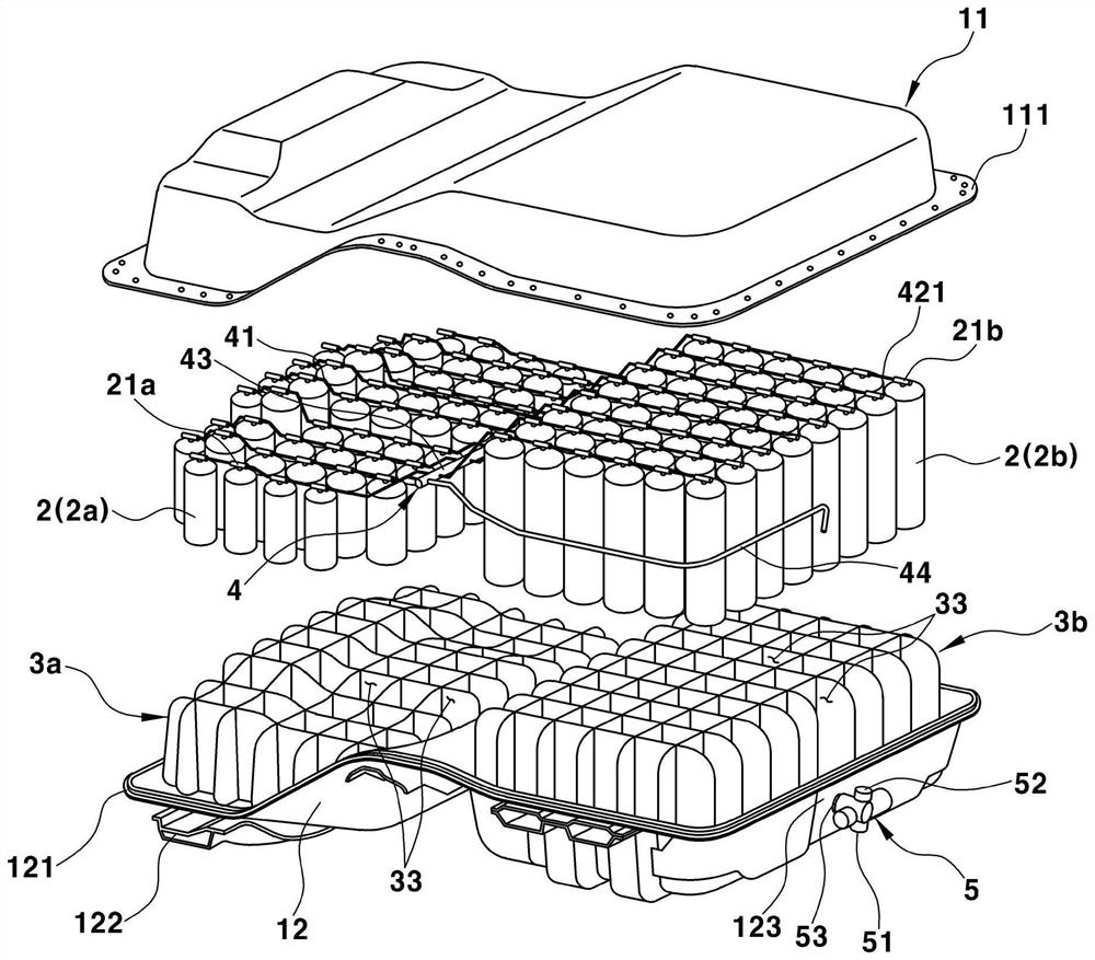
Examples

  • Experimental program(1)

Example Embodiment

[0020]It will be understood that the term "vehicle" or "vehicle" or other similar terms used herein include generalized motor vehicles, such as multiplication including sports multi-purpose vehicles (SUV), bus, trucks, and various commercial vehicles. Tools, aircraft, including a variety of vessels and ships, including hybrid vehicles, electric vehicles, plug-in hybrid vehicles, hydrogen power vehicles, and other alternative fuels (eg, resource other than petroleum) The resulting fuel) vehicle. As mentioned herein, a hybrid vehicle is a vehicle having two or more power sources, such as gasoline power and electric power.
[0021]The terminology used herein is for purposes of describing specific embodiments and is not intended to limit the disclosure. When used herein, singular form "one", "one", and "this" are intended to include multiple forms unless the context further illustrates. It should be further understood that when used in this specification, the term "comprising" and / or "comprising" specifies the present characteristics, overall, steps, operations, elements, and / or components, but do not exclude presence or add one or Multiple other features, overall, steps, operations, components, components, and / or groups. Terms "and / or" include one or more of the various combinations of one or more associated items as used herein.
[0022]The term "approximate" should be understood as in the range of general tolerances in the art, for example, in the range of general tolerances in the art,, unless otherwise specified. "About" can be understood as 10%, 9%, 8%, 7%, 6%, 5%, 4%, 3%, 2%, 1%, 0.5%, 0.1%, 0.05% of the statement. Or in 0.01%. All values ​​provided herein are modified by the term "approximate" unless otherwise clear in the context.
[0023]Hereinafter, the present disclosure will be described as being implemented by those skilled in the art. Such asfigure 1 withfigure 2 As shown, the gas fuel storage device of the present disclosure can include a housing 1 mounted on the body, accommodating a plurality of gas containers 2 in the interior space of the housing 1, and the partition wall portion 3 of the support gas container 2.
[0024]Such asFigure 1 to 4As shown, the housing 1 can have an internal space, and the gas container 2 can be accommodated in the internal space. Specifically, the housing 1 may include a lower casing 11 disposed at the upper casing 11. The housing 1 can have an interior space surrounded by the upper housing 11 and the lower housing 12. referenceFigure 6 The mounting member 122 that is fastened to the body 6 can be disposed on the outer portion of the lower casing 12. The mounting member 122 may be formed to surround the outer portion of the outer portion of the lower casing 12.
[0025]When the lower housing 12 is mounted on the lower side of the body 6 by the mounting member 122, the upper casing 11 is in contact with the lower side of the body 6. Specifically, the lower housing 12 can be mounted on the lower side of the floor panel forming the bottom surface of the body 6, and the upper portion of the upper casing 11 can contact the lower side of the floor panel. The upper flange 111 fastened to the lower housing 12 can be disposed at the lower end of the upper casing 11. The lower flange 121 fastened to the upper housing 11 can be disposed at the upper end of the lower casing 12. The upper flange 111 can be fastened and secured to the lower flange 121 in a state where the upper flange 111 is stacked in the upper side of the lower flange 121.
[0026]In addition, referenceFigure 4 withFigure 5 The housing 1 can be divided into the front housing portion 13 and the rear housing portion 14 relative to the rear wheel suspension 7 mounted on the body 6. Specifically, when the housing 1 is mounted on the body 6, the housing 1 can include a front housing portion 13 disposed in front of the rear wheel suspension 7, and is disposed behind the rear housing portion 14 and integral with the rear wheel suspension 7. The intermediate housing portion 15 is disposed between the front housing portion 13 and the rear housing portion 14.
[0027]Gas vessels 2a and 2b can be housed in the front housing portion 13 and the rear housing portion 14, respectively. In order to place the rear wheel suspension 7 below the intermediate housing portion 15, the bottom surface of the intermediate housing portion 15 may be disposed above the bottom surface of the front housing portion 13 and the bottom surface of the rear housing portion 14 or more. . The rear wheel suspension 7 is a suspension mounted between the rear wheel and the body 6 to isolate the vibration from the road surface. The rear wheel suspension 7 can be disposed below the intermediate housing portion 15 along the left and right directions of the body 6.
[0028]In a common vehicle, the rear seat is disposed at the upper side of the rear wheel suspension, and the trunk is disposed on the upper side behind the rear wheel suspension. Therefore, when the gas fuel storage device is mounted on the vehicle of the existing vehicle, the rear seat can be disposed on the upper side of the rear wheel suspension 7, and the trunk can be disposed on the upper side of the rear wheel suspension 7 ( seeFigure 5 ). Further, the front housing portion 13 can be disposed under the rear seat and the rear housing portion 14 can be disposed below the trunk.
[0029]Gas container 2 can be filled with a gas (ie, gas fuel) used as a vehicle. The gas fuel can be compressed to high pressure (e.g., about 200bar to 250 bar) and stored in the gas container 2. In order to maximize the gas fuel storage capacity of each unit space in the housing 1, the gas container 2 can be vertically disposed in the inner space of the housing 1, and the diameter of the gas container 2 can be limited to about 50 mm to 150 mm. The diameter of the gas container 2 may be the outer diameter of the gas container 2. Gas container 2 can be configured to have a reduced size of the size of the existing large gas container. In other words, the gas container 2 can be a sealing container including a cylindrical cylinder and a circular top portion on both sides of the cylinder.
[0030]The upper end of the gas container 2 can be provided with a tube connection portion 21, and the gas fuel is introduced and discharged through the tube connection portion. The tube connecting portion 21 can be configured to include valves for controlling the introduction and discharge of gas fuel. In order to vertically accommodate the gas container 2 in the housing 1, the partition wall portion 3 can be disposed in the interior space of the housing 1. The partition wall portion 3 can be disposed in the inner space of the housing 1 to divide the interior space into a plurality of storage space 33. Therefore, the partition wall portion 3 can be configured to cause the diaphragm of the grid structure.
[0031]Specifically, the partition wall portion 3 can include a plurality of first diaphragm portions 31 arranged in the left-right direction of the vehicle and a plurality of second diaphragm portions 32 arranged in front-rear direction of the vehicle. The plurality of first diaphragm portions 31 can be arranged in parallel with each other in the left-right direction. The plurality of second diaphragm portions 32 can be arranged in parallel with each other in the front-rear direction. Each second diaphragm portion 32 can be disposed perpendicular to the first diaphragm portion 31. The internal space of the housing 1 can be separated into a plurality of storage space 33 through the first diaphragm portion 31 and the second diaphragm portion 32. The storage space 33 can be a space having a rectangular cross section.
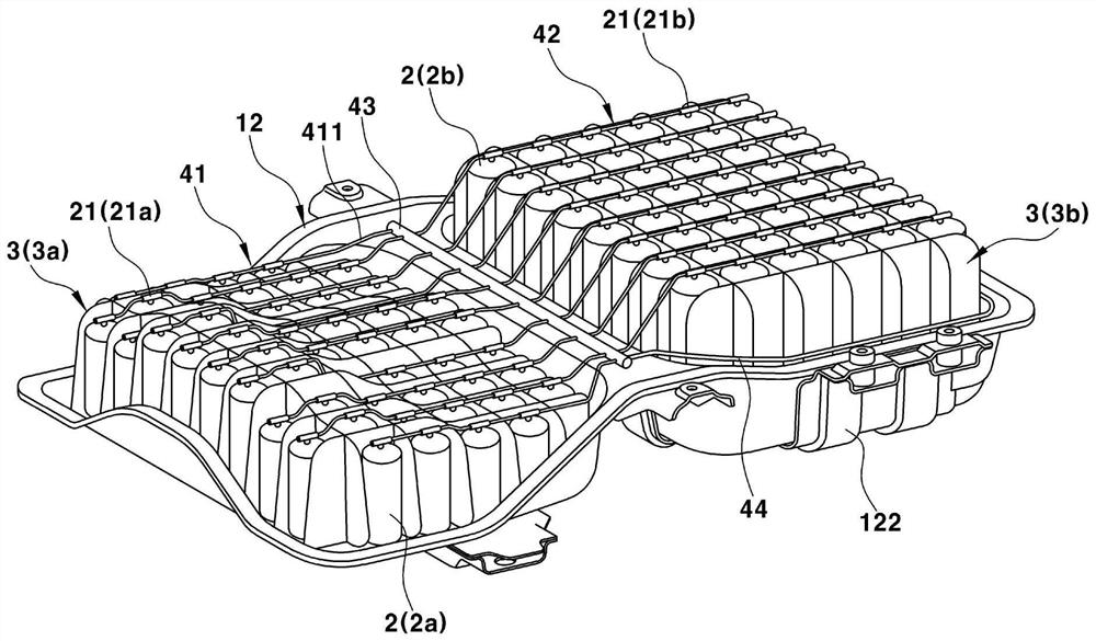
[0032]Gas container 2 can be housed in a plurality of storage space 33. The gas container 2 inserted into the storage space 33 can be adjacent to the gas container 2 in the first diaphragm portion adjacent to the gas container 2 in the plurality of first diaphragm portions 31 and the plurality of second diaphragm portions 32. The second diaphragm portion is in contact with support. Therefore, even when traveling, the flow of the gas container 2 can also be minimized.
[0033]These partition wall portions 3 can be disposed in the front housing portion 13 and the rear housing portion 14, respectively. Specifically, the partition wall portion 3 disposed in the front housing portion 13 may be a front partition wall portion 3a, and the partition wall portion 3 disposed in the rear housing portion 14 may be a rear partial wall portion 3b. In order to connect the gas container 2 accommodated in the interior space of the housing 1 to be disposed outside the housing 1, one side of the housing 1 may include a tube portion 4 connected to the gas container 2. Valve 5.
[0034]referencefigure 2 withFigure 5 The multi-valve 5 can be disposed outside the housing 1. Specifically, the multi-valve 5 can be disposed from the rear side portion of the lower casing 12. The position of the multi-valve 5 can be changed as needed. In other words, the multi-valve 5 may be disposed anywhere in the housing 1, whether it is the upper side, the lower side, and the side, and the like.
[0035]The multi-valve 5 can be configured to include: the first valve 51, the first valve discharges the gas fuel stored in the gas container 2 to the engine; the second valve 52, the second valve will supply gas supplied from the outer portion of the housing 1 Fuel introduces gas container 2; and port 53, which is coupled to the multi-tube 44 of the tube portion 4. In other words, the multi-valve 5 can be configured to include a first valve 51 which can be connected to the engine, a second valve 52 which can be connected to an external gas supply device, and a port 53 which can be coupled to the gas container 2. Both the first valve 51 and the second valve 52 can be connected to the plurality of tube 44 via the port 53.
[0036]The rear side portion of the lower housing 12 can include a mounting portion 123, and the port 53 is assembled on the mounting portion. Port 53 can be mounted in the mounting portion 123 to penetrate the rear side of the housing 12. Therefore, the mounting portion 123 can be provided with a hole 124, and port 53 can be assembled into the aperture.
[0037]referenceFigure 1 to 4In addition to the multi-tube 44, the tube portion 4 can include the front tube portion 41, the rear tube portion 42, and the intermediate tube 43. The front tube portion 41 can be connected to all gas containers accommodated in the front housing portion 13 (hereinafter, referred to as "front gas containers"). Specifically, the front tube portion 41 can be coupled to all tube connecting portions 21a disposed on the upper side portion of the front gas container 2a. The front tube portion 41 can realize gas delivery between the tube connection portion 21a. The front tube portion 41 can be coupled to the intermediate tube 43 such that the gas transmission between the front tube portion 41 and the intermediate tube 43 can be realized.
[0038]referenceFigure 4 The front gas container 2a can be disposed in the front housing portion 13. Further, the front tube portion 41 can be configured as a front tube 411 for a connection between a series of gas containers arranged in the front-rear direction in the front-rear direction. Specifically, the front tube 411 can be coupled between the tube connection portion 21a of the front gas container 2a. The front gas container 2a can be attached to a gas container disposed in a straight line in a front-rear direction via a front tube 411. The front tube 411 can be connected to the tube connection portion 21a and the intermediate tube 43.
[0039]The rear tube portion 42 can be coupled to all gas containers accommodating in the rear housing portion 14 (hereinafter referred to as "rear gas containers"). Specifically, the rear tube portion 42 can be coupled to all tube connecting portions 21b disposed on the upper side of the rear gas container 2b. The rear tube portion 42 can realize gas transmission between the tube connection portion 21b. The rear tube portion 42 can be coupled to the intermediate tube 43 to enable gas transmission between the rear tube portion 42 and the intermediate tube 43.
[0040]referenceFigure 4 After the rear gas container 2b can be arranged in the rear housing portion 14. Further, the rear tube portion 42 can be configured to be rear tube 421 for connection between a series of gas containers arranged in the front and rear direction in the rear gas container 2b. Specifically, the rear tube 421 can be coupled between the tube connection portion 21b of the rear gas container 2b. The rear gas container 2b can be attached to a gas container disposed on a straight line in front-rear direction via a rear tube 421. The rear tube 421 can be connected to the tube connection portion 21b and the intermediate tube 43.
[0041]The intermediate tube 43 can be disposed in the intermediate housing portion 15 and can be coupled to the front tube portion 41 and the rear tube portion 42. Further, the intermediate tube 43 can be coupled to the multi-tube 44. Further, the multi-tube 44 can be coupled to the port 53 of the multi-valve 5. In other words, the multi-tube 44 can be disposed between the intermediate tube 43 and the multi-valve 5 to be connected to the port 53 and the intermediate tube 43 of the multi-valve 5.
[0042]In the gas fuel storage device as described above, since the housing 1 can be mounted on the lower side of the body 6, the gas storage capacity can be easily ensured than the existing gas container, the internal space of the body 6 does not need to be set. The support body of the existing large gas container is mounted, and the internal space and trunk of the vehicle can be prevented from being reduced due to the housing 1, and therefore, the internal contained inner contained in the vehicle can be prevented from deteriorating.
[0043]Further, the gas fuel storage device can utilize the existing battery housing for the electric vehicle without re-designing the housing 1, and thus can reduce the investment cost. For example, the battery power terminal is typically mounted at the rear side of the battery housing. Therefore, the multi-valve 5 can be mounted on the rear side of the battery housing mounted with a power supply terminal without having to modify the battery housing separately. Further, with the case of using a small size of the gas container 2, the gas fuel storage device has an advantage of the gas container having the gas container with the existing gas container 2.
[0044]Although exemplary embodiments of the present disclosure are described in detail above, the scope of the present disclosure is not limited thereto, but may include several of the present disclosure of the present disclosure by the claims by those skilled in the art. Modify and change.

PUM

no PUM

Description & Claims & Application Information

We can also present the details of the Description, Claims and Application information to help users get a comprehensive understanding of the technical details of the patent, such as background art, summary of invention, brief description of drawings, description of embodiments, and other original content. On the other hand, users can also determine the specific scope of protection of the technology through the list of claims; as well as understand the changes in the life cycle of the technology with the presentation of the patent timeline. Login to view more.
Why Eureka
Try Eureka