Positioning assembly suitable for electromechanical equipment mounting

A technology for positioning components and electromechanical equipment, applied in the direction of adopting mechanical devices, mechanical measuring devices, measuring devices, etc., can solve problems such as out-of-synchronization of adjustment methods, offset of electromechanical equipment, and inability to detect the balance of electromechanical equipment, etc., to achieve the convenience of use Effect

Active Publication Date: 2021-04-13
WUXI INST OF COMMERCE
View PDF10 Cites 0 Cited by
  • Summary
  • Abstract
  • Description
  • Claims
  • Application Information

AI Technical Summary

Problems solved by technology

[0005] In order to solve the above technical problems, the present invention provides a positioning assembly suitable for the installation of electromechanical equipment to solve the problem that when the installation height is adjusted, the adjustment method is not synchronized, which may easily cause the electromechanical equipment to shift, and it can only adjust the level of the electromechanical equipment. The balance degree of a position in the direction is detected, and the balance degree of different positions on the electromechanical equipment cannot be detected

Method used


Image

  • Positioning assembly suitable for electromechanical equipment mounting
  • Positioning assembly suitable for electromechanical equipment mounting
  • Positioning assembly suitable for electromechanical equipment mounting

Examples


Embodiment

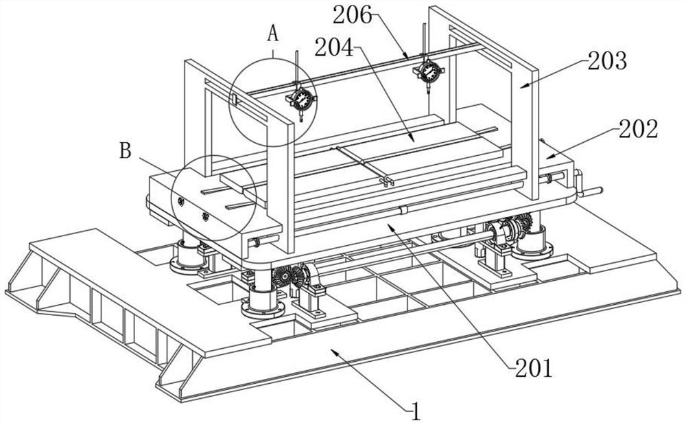
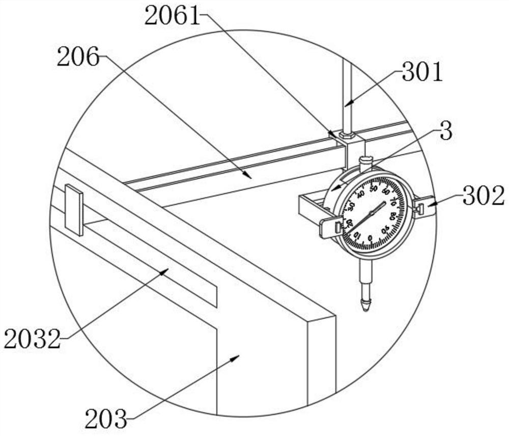
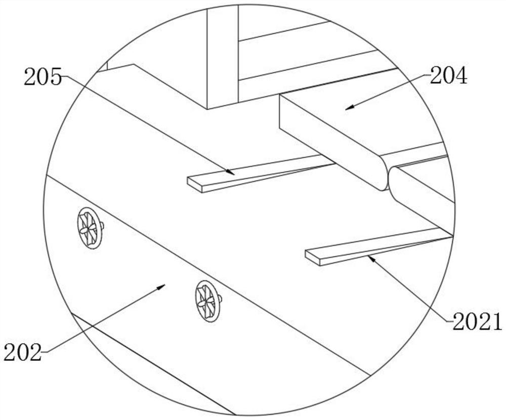
[0034] as attached figure 1 to attach Figure 9 Shown:

[0035] The present invention provides a positioning assembly suitable for installation of electromechanical equipment, including a base 1 and a positioning plate frame 2; two sets of support cylinders 101 and four sets of support rods 102 are installed on the base 1, and the four sets of support rods 102 are respectively slidably inserted into the The shaft sleeve 105 is located at the four corners of the base 1, and the top ends of the support cylinder 101 and the support rod 102 are respectively fixedly connected to the lower connecting plate 201 by screws, and four sets of limit stop rods 106 are fixedly inserted on the base 1. , and the limit bar 106 is set on the inner side of the strut 102 respectively, the positioning plate frame 2 includes a lower connecting plate 201, a U-shaped frame 202, a clamping frame 203 and a positioning strut 204, and the U-shaped frame 202 is connected to the lower On the top side of ...


PUM


Abstract

The invention provides a positioning assembly suitable for electromechanical equipment mounting. The positioning assembly comprises a base and a positioning plate frame. Two sets of supporting cylinders and four sets of supporting rods are mounted on the base, and the four sets of supporting rods are inserted in shaft sleeves in a sliding manner correspondingly and located at the four end corners of the base. The positioning plate frame comprises a lower connecting plate, a U-shaped frame, clamping frames and positioning supporting plates, the U-shaped frame is connected to the top side of the lower connecting plate, the two sets of clamping frames are arranged and are mounted at the two ends of the U-shaped frame in an aligned and sliding manner correspondingly, the four sets of positioning supporting plates are arranged, and the middles of the positioning supporting plates are rotationally mounted on the U-shaped frame through fixing shafts. The supporting cylinders on the base are used for pushing the whole positioning plate frame to move upwards, and meanwhile the four sets of supporting rods are driven to move synchronously and upwards, so that the whole positioning plate frame is subjected to synchronous and upward stable lifting adjustment. The heights of probes at the bottom ends of dial indicators are adjusted through vertical adjusting screws at the rear ends of dial indicator clamping frames, and the positions of the probes of the dial indicators are changed by adjusting the positions of cross beam frames in longitudinal grooves and the positions of sliding mounting blocks.

Description

technical field [0001] The invention belongs to the technical field of electromechanical equipment installation, and more specifically relates to a positioning assembly suitable for the installation of electromechanical equipment. Background technique [0002] With the development of mechanical automation, most companies today are using automated electromechanical equipment to improve production efficiency. However, since most electromechanical equipment installations require professionals to carry out, the electromechanical installation industry has emerged as the times require. Electromechanical equipment Generally, the requirements for positioning accuracy during installation are very high. [0003] For example, in the patent with the application number: CN201921632159.X, a positioning instrument for the installation of electromechanical equipment is disclosed, including a horizontal positioning plate. The lower surface of the horizontal positioning plate is fixedly conne...

Claims


Application Information

Patent Timeline
Patent Type & Authority Applications(China)
IPC IPC(8): B25B11/02B25H1/10B25H1/16B25B27/00G01B5/00
CPCB25B11/02B25H1/10B25H1/16B25B27/00G01B5/00G01B5/0002
Inventor 李景魁王丹净
Owner WUXI INST OF COMMERCE
Why Eureka
Try Eureka