
A Design Method of Unidirectional Acoustic Array with Broadband Constant Main Beam

A design method and acoustic array technology, applied to a direction finder using ultrasonic/sonic/infrasonic waves, a system for determining direction or offset, and measuring directions such as ultrasonic/sonic/infrasonic waves, which can solve the problem of large deviations in wide-frequency domain measurement values ​​and design Inconsistency, unfavorable distribution and adjustment of key parameters of the array to achieve the effect of improving measurement accuracy

Active Publication Date: 2022-06-24
CHINA RAILWAY DESIGN GRP CO LTD
View PDF5 Cites 0 Cited by
  • Summary
  • Abstract
  • Description
  • Claims
  • Application Information

AI Technical Summary

Problems solved by technology

[0003] However, there are still deficiencies in the use of end-fire arrays for directional monitoring in complex acoustic environments
On the one hand, previous related research and array design focused on improving the sharpness of the main beam angle, and there is no effective array design method for noise directional monitoring at any wide angle, which is not conducive to adjusting the key parameters of the array according to the actual monitoring scene and sound source distribution. ; On the other hand, due to the performance difference between the microphones, the error caused by the sound scattering of the microphone shell, etc., the theoretically designed end-fire array receives a response that varies with frequency in actual use, which is inconsistent with the design. large deviation

Method used


Image

  • A Design Method of Unidirectional Acoustic Array with Broadband Constant Main Beam
  • A Design Method of Unidirectional Acoustic Array with Broadband Constant Main Beam
  • A Design Method of Unidirectional Acoustic Array with Broadband Constant Main Beam

Examples


Embodiment

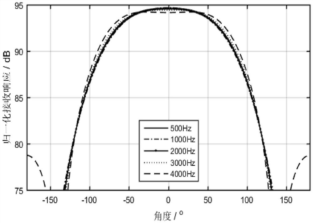
[0073] Design case of unidirectional acoustic array for directional monitoring of noise in construction site: In order to monitor the internal noise of the construction site and suppress the interference of external background noise, a unidirectional acoustic array needs to be designed, and attenuation within 40 degrees on both sides of the main axis of the array is required The attenuation does not exceed 1dB, the attenuation does not exceed 6dB at 90 degrees, the main beam angle of -3dB (that is, the half power angle) is 70 degrees, the monitoring frequency range is 500-4000Hz, and the number of microphones is 4.

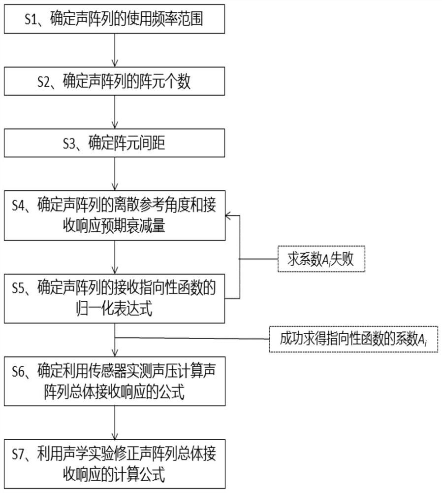
[0074] see figure 1 and figure 2 , the design method includes the following steps:

[0075] S1. Determine the frequency range of the acoustic array:

[0076] The lower frequency limit of the acoustic array is F 1 , the upper limit of the use frequency is F 2 , where F 1 ≧16Hz, F 2 ≦20000Hz. In this embodiment, the use frequency lower limit F of the acousti...


PUM


Abstract

The invention discloses a unidirectional acoustic array design method with a broadband constant main beam. According to key parameters such as the operating frequency range of the acoustic array, the number of array element microphones, and the expected receiving response of discrete reference angles, constrained linear programming is adopted. Methods The normalized expression of the receiving directivity function of the acoustic array was established, and the formula for calculating the overall receiving response of the acoustic array by using the measured sound pressure of the microphone was established through the spatial filter weighting of the average sound pressure and the equalized sound pressure gradient, and the overall receiving response of the array was calculated by acoustic experiments. The calculation formula of the receiving response is corrected, so that the receiving response of the array to the incident sound waves at different angles tends to be consistent with the expectation. The present invention overcomes the defects existing in the existing unidirectional acoustic array design, and is applied to the array design in the fields of sound source localization, noise directional monitoring and intelligent audio recognition, and has the advantages of artificially controllable main beam angle in a wide frequency range and consistency of receiving response Strong and high measurement accuracy.

Description

technical field [0001] The invention belongs to the field of acoustic measurement, and relates to a unidirectional sound array design method with a broadband constant main beam, which is suitable for sound source localization, noise directional monitoring, intelligent audio recognition and the like. Background technique [0002] The acoustic array is the key equipment for sound source identification and detection. There are two basic types of acoustic arrays: side-fire arrays and end-fire arrays. The side-beam array is a line array or area array composed of microphones. Using the delay difference or phase difference between the sound waves reaching different microphones, the propagation direction of the sound wave is judged. direction) is not unique, the main direction of the linear edge shot array is the infinite ray directions of the geometric center of the array as the endpoint and perpendicular to the array connection, and the surface edge shot array (such as circle, re...

Claims


Application Information

Patent Timeline
Patent Type & Authority Patents(China)
IPC IPC(8): G01S5/18G01S3/802G01H17/00G10L15/00
CPCG01S5/18G01S3/80G01H17/00G10L15/00
Inventor 胡文林何宾刘冀钊齐春雨王少林姜博龙
Owner CHINA RAILWAY DESIGN GRP CO LTD
Learn More