Traveling route generation device and vehicle control device

A technology of vehicle control device and driving path, which is applied in the traffic control system of road vehicles, vehicle position/route/height control, vehicle components, etc., and can solve the problems of deterioration of ride comfort, uneven precision, and unsmooth driving Path and other issues

Active Publication Date: 2021-04-23
MITSUBISHI ELECTRIC CORP
View PDF6 Cites 2 Cited by
  • Summary
  • Abstract
  • Description
  • Claims
  • Application Information

AI Technical Summary

Problems solved by technology

[0003] However, when solving the driving route through discrete point sequences, if these discrete point sequences are directly used, a smooth driving path cannot be obtained due to uneven accuracy, and sometimes there will be problems such as deterioration of ride comfort.

Method used


Image

  • Traveling route generation device and vehicle control device
  • Traveling route generation device and vehicle control device
  • Traveling route generation device and vehicle control device

Examples


Embodiment approach 1

[0037]

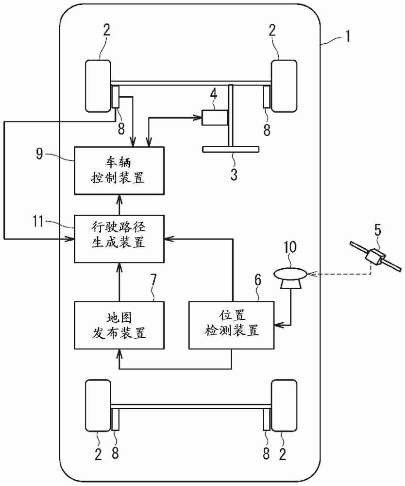
[0038] figure 1 It is a diagram showing the overall configuration of a vehicle system including the travel route generation device 11 according to Embodiment 1 of the present invention.

[0039] Such as figure 1 As shown, the vehicle system is applied to a vehicle 1 provided with wheels 2 and a steering wheel 3, and includes a steering device 4, an antenna 10, a position detection device 6, a map distribution device 7, a vehicle speed sensor 8, a vehicle control device 9, a driving route generation device 11, and a yaw rate sensor not shown.

[0040] It should be noted that, in figure 1 In this embodiment, the position detection device 6 and the map distribution device 7 are configured independently, but they may also be configured integrally. Furthermore, the travel route generation device 11 and the vehicle control device 9 are configured independently, but they may also be configured integrally.

[0041] The steering device 4 is composed of, for example, an E...

Embodiment approach 2

[0098] In Embodiment 1, the case where the weight of the control reference point Pref is set to be greater than the weight of other points ahead of the vehicle 1 has been described. In Embodiment 2 of the present invention, it is described that the control reference point Pref is the center of gravity position of the vehicle 1, and the travel route generation device 11 calculates the tangent and curvature of the travel route at the control reference point Pref, and the vehicle control device 9 calculates the tangent and curvature of the travel route at the control reference point Pref. The case where the command steering angle θref is calculated based on the tangent and curvature of the traveling path. It should be noted that the configurations of the vehicle 1 , travel route generation device 11 , and vehicle control device 9 in the second embodiment are the same as those in the first embodiment, and therefore detailed descriptions are omitted here.

[0099]

[0100]

[0...

Embodiment approach 3

[0126]In Embodiments 1 and 2, the case where the control reference point Pref is a point in front of the vehicle 1 or the center of gravity of the vehicle 1 has been described. In Embodiment 3 of the present invention, a case where there are a plurality of control reference points Pref will be described. It should be noted that the configurations of the vehicle 1 , travel route generation device 11 , and vehicle control device 9 in the third embodiment are the same as those in the first embodiment, and therefore detailed descriptions thereof are omitted here.

[0127] Specifically, the steering control of the vehicle 1 uses model predictive control. In model predictive control, a dynamic vehicle model that mathematically represents the dynamics of the vehicle is used to predict the state from the current time t to Th, and solve the optimization problem at regular intervals, thereby calculating the optimal command steering angle θref, where the optimization problem is a proble...


PUM


Abstract

The purpose of the present invention is to provide a traveling route generation device capable of generating an accurate traveling route, and a vehicle control device for controlling traveling of a vehicle such that the vehicle travels along a traveling route generated by the traveling route generation device. A traveling route generation device (11) according to the present invention comprises: a traveling region information acquisition unit (15) for acquiring traveling region information, which is information on a region where a vehicle travels; and a traveling route generation unit (16) for generating, on the basis of the traveling region information, information on a traveling curve representing a route along which the vehicle should travel forward. Output of the traveling route generation unit (16) is given to a vehicle control unit (21) for controlling steering of the vehicle. The traveling route generation unit (16) generates the information on the traveling curve by applying larger weighting to traveling region information on a range used for the steering control among the traveling region information than to traveling region information on a range not used for the steering control.

Description

technical field [0001] The present invention relates to a travel route generation device for generating a travel route on which a vehicle travels, and a vehicle control device for controlling travel of a vehicle so as to travel along the travel route generated by the travel route generation device. Background technique [0002] In order to support the driving of the vehicle or to automatically drive the vehicle, it is necessary to detect a road on which the vehicle should travel or an area where the vehicle can travel, generate a travel route as the route on which the vehicle should travel, and control the vehicle so as to travel along the generated travel route. Furthermore, in order to control the vehicle in such a way as to follow the generated travel route, the method of using not only the position error between the travel route and the vehicle, but also information such as the angle error and curvature of the travel route and the vehicle can make the vehicle follow the t...

Claims


Application Information

Patent Timeline
Patent Type & Authority Applications(China)
IPC IPC(8): G08G1/09B62D6/00G08G1/0968G08G1/16
CPCB62D15/025G05D1/0212G05D2201/0213G08G1/0968
Inventor 北野弘明
Owner MITSUBISHI ELECTRIC CORP
Why Eureka
Try Eureka