
A Continuously Variable Stiffness Ball Joint Based on Pneumatics

A ball joint and stiffness technology, applied in the field of robotics, can solve the problems of low stiffness and poor bearing capacity of flexible robots, and achieve the effect of large stiffness and bearing capacity

Active Publication Date: 2022-03-11
HARBIN INST OF TECH
View PDF7 Cites 0 Cited by
  • Summary
  • Abstract
  • Description
  • Claims
  • Application Information

AI Technical Summary

Problems solved by technology

[0003] The present invention aims to solve the problems of low rigidity and poor load-carrying capacity of existing flexible robots, and further provides a continuously variable stiffness ball joint based on aerodynamics

Method used


Image

  • A Continuously Variable Stiffness Ball Joint Based on Pneumatics
  • A Continuously Variable Stiffness Ball Joint Based on Pneumatics
  • A Continuously Variable Stiffness Ball Joint Based on Pneumatics

Examples


specific Embodiment approach 1

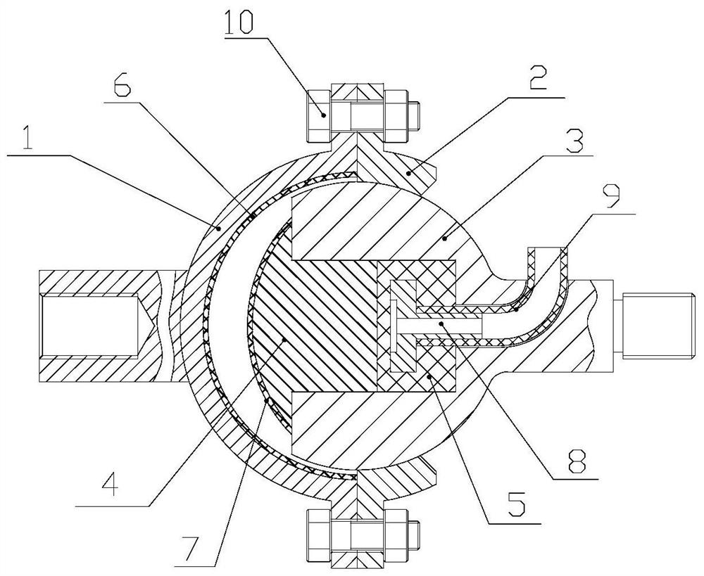
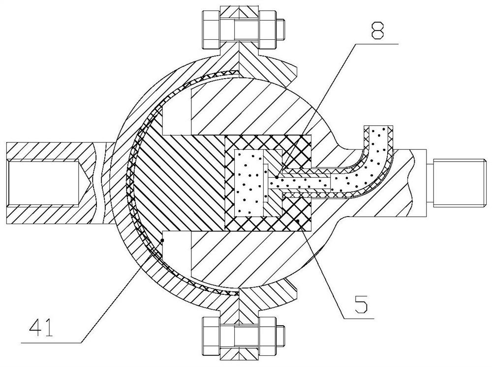
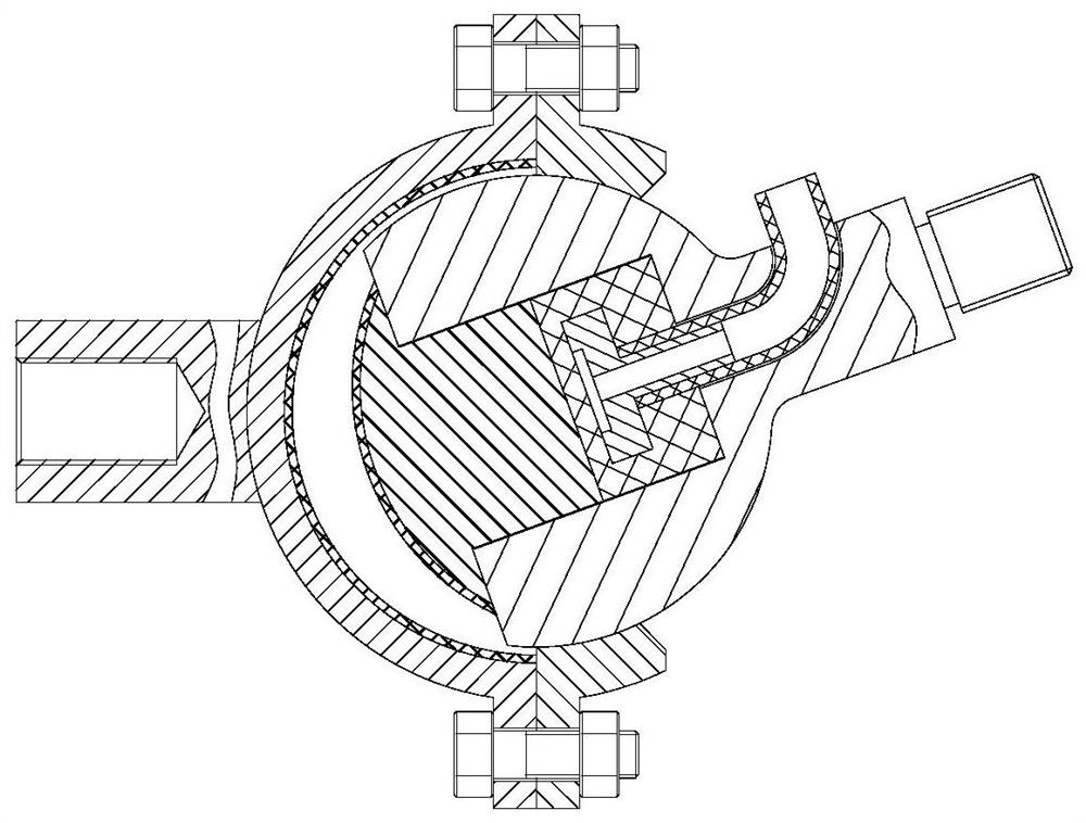
[0022] Specific implementation mode one: combine Figure 1~5 Describe this embodiment, a continuously variable stiffness ball joint based on pneumatics, which includes a left ball socket 1, a right ball socket 2, a support ball head 3, a friction ball head 4 and a silicone sealing cavity 5, wherein the left ball socket 1 It is fixedly connected with the right ball socket 2 and forms a cavity. The supporting ball head 3 is installed in the cavity in cooperation with rotation. There is a groove on the head 3, and the opening end of the groove is set towards the left ball socket 1. The silicone sealing cavity 5 is installed at the bottom of the groove, and one end of the friction ball head 4 is inserted into the groove. In the groove and in contact with the silica gel sealing cavity 5 without gaps, the shape of the other end is set along with the inner wall of the left ball socket 1. The inner wall of the left ball socket 1 is fixed with a ball socket friction layer 6, and the ot...


PUM


Abstract

The utility model relates to a continuously variable rigidity ball joint based on aerodynamics, which belongs to the technical field of robots. The invention solves the problems of low rigidity and poor carrying capacity of the existing flexible robot. In the state of joint lock, the outer wall of the support ball head is in close contact with the inner wall of the right ball socket, a groove is opened on the support ball head, and the opening end of the groove is set facing the left ball socket, and the silicone sealing cavity is installed at the bottom of the groove , one end of the friction ball head is inserted into the groove and is in contact with the silica gel sealing cavity without gaps, the shape of the other end is set along with the inner wall of the left ball socket, and the inner wall of the left ball socket is fixed with a ball The other end of the friction ball head is fixed with a ball head friction layer, and an air core is installed inside the silica gel sealed cavity, and the air core communicates with an external air source through a trachea. Since the frictional force is directly proportional to the pressure of the high-pressure gas introduced into the silicone sealed cavity, continuous adjustment of the stiffness can be realized. The ball joint of the present application can achieve very large stiffness and bearing capacity.

Description

technical field [0001] The invention relates to a pneumatically-based continuously variable rigidity ball joint, which belongs to the technical field of robots. Background technique [0002] Due to its good compliant structure, flexible and continuous deformation characteristics, high safety and environmental adaptability, soft robots have great application potential in medical rehabilitation, emergency rescue, resource survey, pipeline inspection and military investigation. . However, due to the problems of low rigidity and poor carrying capacity of soft robots, its application has great limitations. In order to improve the stiffness and carrying capacity of soft robots and expand their application range, the variable stiffness of soft robots has become a research hotspot for a time. Contents of the invention [0003] The present invention aims to solve the problems of low rigidity and poor load-carrying capacity of existing flexible robots, and further provides a pneum...

Claims


Application Information

Patent Timeline
Patent Type & Authority Patents(China)
IPC IPC(8): B25J17/02
CPCB25J17/0275
Inventor 杨飞岳洪浩阮琪李前程
Owner HARBIN INST OF TECH
Learn More