Detachable battery fixing frame for new energy automobile based on sliding

A new energy vehicle and battery fixing technology, which is applied in the direction of electric vehicles, secondary batteries, battery pack components, etc., can solve the problems of endangering the driver's personal safety, reducing the service life of the battery, and inconvenient disassembly of the battery, so as to solve the inconvenience of maintenance and replacement , Improve the safe service life and improve the convenience of use

Inactive Publication Date: 2021-05-07
韩春祥
View PDF0 Cites 5 Cited by
  • Summary
  • Abstract
  • Description
  • Claims
  • Application Information

AI Technical Summary

Problems solved by technology

[0002] The battery of a new energy vehicle is fixed inside the car by a fixed frame, but there is no shock absorber on the existing fixed frame, which will cause vibrations due to continuous bumps during the driving process of the car, and the fixed frame follows the bumps of the car, which will easily cause the battery to be stuck in the fixed frame. The internal vibration is damaged, and even the batteries collide with each other to explode, causing danger and endangering the personal safety of the driver. Moreover, the battery is not easy to disassemble from the fixed frame, and it is inconvenient to maintain and replace the battery. A large amount of heat is generated during the time, which increases the temperature in the fixed frame, softens or even melts the protective shell on the battery surface, resulting in electric shock when the wire contacts, causing explosion hazards, and reducing the service life of the battery.

Method used


Image

  • Detachable battery fixing frame for new energy automobile based on sliding
  • Detachable battery fixing frame for new energy automobile based on sliding
  • Detachable battery fixing frame for new energy automobile based on sliding

Examples


Embodiment 1

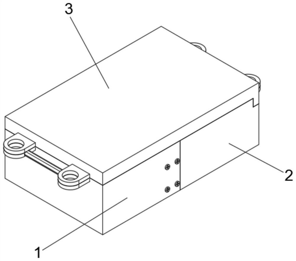
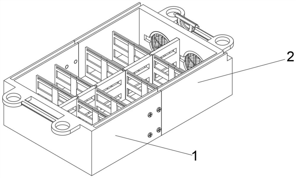
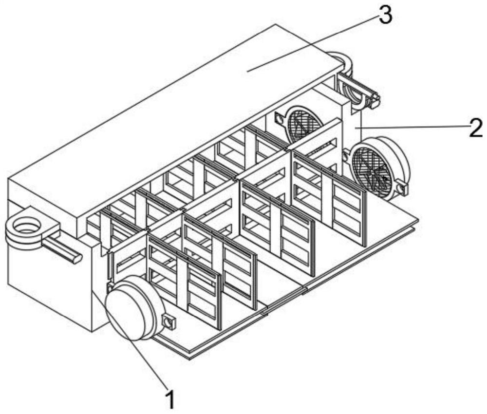
[0056] see Figure 1-Figure 12 As shown, a sliding and detachable battery fixing frame for new energy vehicles is provided, a clamping device 1, a splicing device 2 is symmetrically provided on one side of the clamping device 1, and a top slide is provided on the top of the clamping device 1 and the splicing device 2. connecting device 3;

[0057] The clamping device 1 includes a clamping fixed frame 11, the center line of both sides of one end of the clamped fixed frame 11 is provided with a fixed frame side clamping groove 112 with several screw grooves on the inner wall, and the clamped fixed frame 11 is provided on one side of the inner wall. Cooling devices 14 are arranged symmetrically on both sides of the axis. The cooling device 14 includes a circular motor casing 141. Both sides of the motor casing 141 are provided with connecting ears 142. One side of the connecting ears 142 is fixed to the inner wall of the clamping frame 11 by bolts. A motor 143 is arranged inside...


PUM


Abstract

The invention relates to the technical field of battery fixing frames, and concretely relates to a detachable battery fixing frame for a new energy automobile based on sliding. The fixing frame comprises a clamping device, splicing devices are symmetrically arranged on one side of the clamping device, top sliding connection devices are arranged at the tops of the clamping device and the splicing devices, the clamping device comprises a clamping fixing frame, and cooling devices are symmetrically arranged on the two sides of the central axis of one side of the inner wall of the clamping fixing frame. Each cooling device comprises an annular motor shell, a motor is arranged in the motor shell, a rotating shaft is arranged at the circle center of one end of the motor, fan blades are arranged at one ends of the rotating shafts, each splicing device comprises a splicing fixing frame, and a battery is not convenient to detach from the fixing frame, and after an automobile is driven for a long time, a large amount of heat is generated between the batteries to increase the temperature in the fixing frame and soften protective shells on the surfaces of the batteries, so that electric shock and explosion danger are caused by wire contact, and the service life of the batteries is shortened.

Description

technical field [0001] The invention relates to the technical field of battery fixing frames, in particular to a sliding and detachable battery fixing frame for new energy vehicles. Background technique [0002] The battery of the new energy vehicle is fixed inside the car through the fixed frame, but there is no shock absorbing device on the existing fixed frame, which will cause vibrations due to continuous bumps during the driving process of the car, and the fixed frame follows the bumps of the car, which will easily cause the battery to be stuck in the fixed frame. The internal vibration is damaged, and even the batteries collide with each other to explode, causing danger and endangering the personal safety of the driver. Moreover, the battery is not easy to disassemble from the fixed frame, and it is inconvenient to maintain and replace the battery. A large amount of heat is generated during the time, which increases the temperature inside the fixed frame, softens or ev...

Claims


Application Information

Patent Timeline
Patent Type & Authority Applications(China)
IPC IPC(8): H01M50/249H01M50/242H01M50/244H01M10/613H01M10/625H01M10/6563B60L50/64
CPCB60L50/64H01M10/613H01M10/625H01M10/6563Y02E60/10Y02T10/70
Inventor 韩春祥
Owner 韩春祥
Why Eureka
Try Eureka