HDMI optical fiber transmission device

A technology of optical fiber transmission and transmission method, which is applied in the direction of optical fiber transmission, TV system adapted to optical transmission, cable transmission adaptation, etc., and can solve problems such as difficult implementation and troublesome equipment operation

Pending Publication Date: 2021-05-07
GUANGZHOU DTECH ELECTRONICS TECH CO LTD
View PDF0 Cites 2 Cited by
  • Summary
  • Abstract
  • Description
  • Claims
  • Application Information

AI Technical Summary

Problems solved by technology

[0003] The existing long-distance transmission generally uses HDMI network cable extenders, but the distance that HDMI network cable extenders can extend is generally about 120 meters at most. If the cascade uses HDMI network cable extenders to connect images in series, if there is an HDMI image processing device in the middle , both the front end and the rear end can only add a pair of HDMI network cable extenders. In this case, the longest transmission distance is about 200 meters
If it exceeds this distance, it will be difficult to achieve
Therefore, the existing technology is difficult to meet people's needs
[0004] In addition, long-distance transmission is cumbersome to operate on devices that need to be controlled, such as the need to control the start-up and playback of remote Blu-ray players, etc. How to realize the transmission of remote control device signals is also a market demand problem that needs to be solved

Method used


Image

  • HDMI optical fiber transmission device
  • HDMI optical fiber transmission device
  • HDMI optical fiber transmission device

Examples


Embodiment Construction

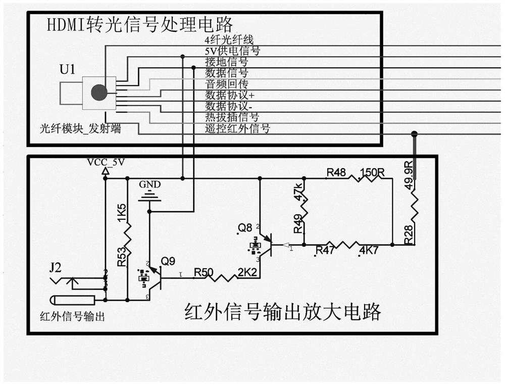
[0023] The transmission method of the HDMI signal of the present invention comprises the following steps:

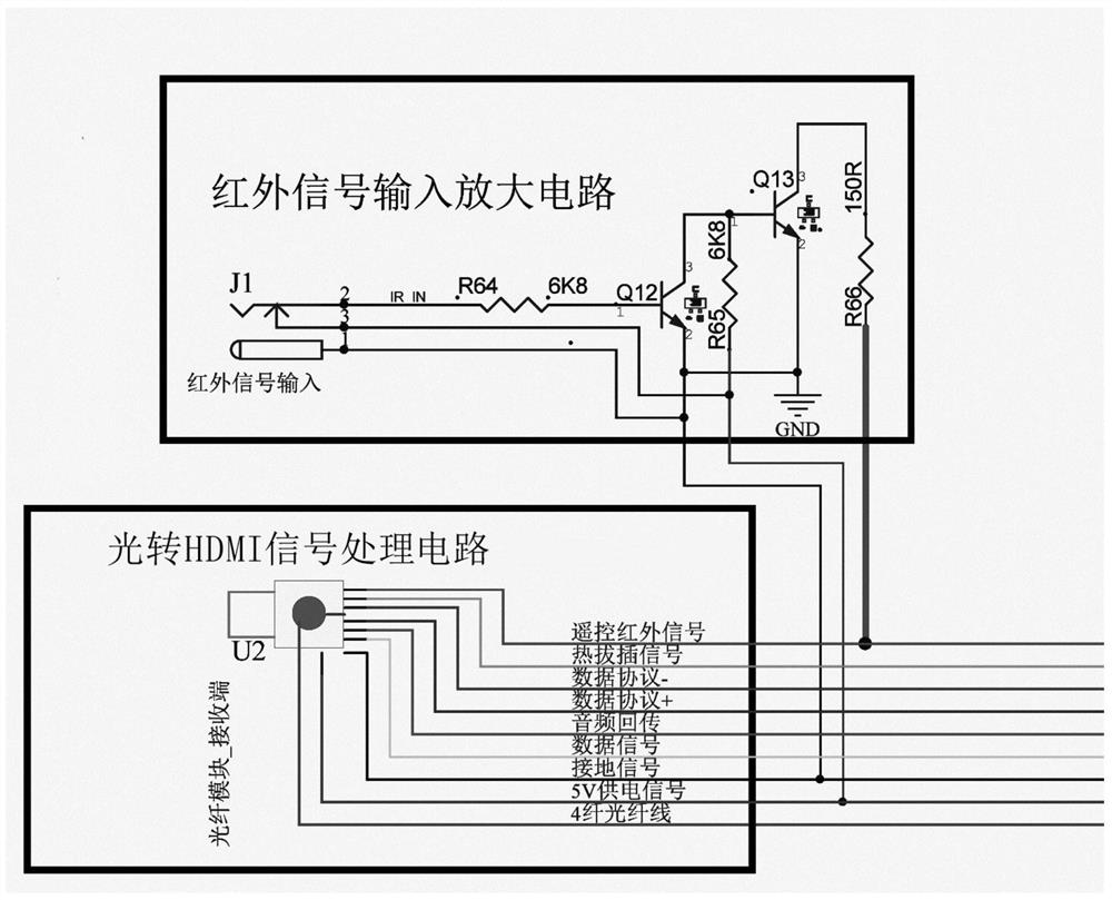
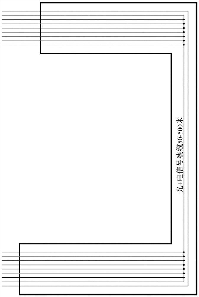
[0024]Set the signal transmitting part and the signal receiving part, and the transmission line part composed of the optical fiber line and the cable connected between the signal transmitting part and the signal receiving part, and the signal transmitting part is composed of an HDMI-to-optical signal processing circuit and a remote control infrared signal output amplifier circuit , the signal receiving part is composed of an optical-to-HDMI signal processing circuit and a remote control infrared signal input amplifier circuit, and the HDMI-to-optical signal processing circuit converts 4 pairs of HDMI digital signals into 4 multi-mode optical signals for transmission, and It is transmitted by multi-mode fiber optic cable, other signals of HDMI are transmitted by copper wire, other signals of HDMI include power supply signal, ground signal, data signal, audio return signal,...


PUM


Abstract

The invention discloses an HDMI signal transmission method, and the method comprises the following steps: arranging a signal transmitting part, a signal receiving part and a transmission line part consisting of an optical fiber line and a cable, wherein the signal transmitting part consists of an HDMI light conversion signal processing circuit and a remote control infrared signal output amplifying circuit, and the signal receiving part is composed of a light-to-HDMI signal processing circuit and a remote control infrared signal input amplification circuit; enabling the HDMI light-to-HDMI signal processing circuit to convert HDMI digital signals into light signals and send the light signals out; transmitting the light signals through a multimode optical fiber cable, and transmitting other signals of the HDMI through copper wires; enabling the light-to-HDMI signal processing circuit to convert the received light signal into an HDMI digital signal and transmit the HDMI digital signal to display equipment; enabling the remote control infrared signal input amplification circuit to amplify a remote control infrared signal sent by a remote controller and transmit the amplified remote control infrared signal to the signal emission part through a remote control infrared signal line. The invention further discloses an HDMI optical fiber transmission device. According to the invention, remote transmission of HDMI signals is effectively realized, and transmission of signals of remote control equipment is realized.

Description

technical field [0001] The invention relates to the technical field of HDMI optical fiber transmission, in particular to an HDMI optical fiber transmission device. Background technique [0002] HDMI high-definition signal can display images more clearly. For larger display devices, the quality of HDMI signal images is superior to VGA and AV signals, but the transmission distance of HDMI signals is limited, and the signal strength of HDMI signal sources The differences in the quality of HDMI cables and HDMI image processing equipment lead to different transmission distances. [0003] The existing long-distance transmission generally uses HDMI network cable extenders, but the distance that HDMI network cable extenders can extend is generally about 120 meters at most. If the cascade uses HDMI network cable extenders to connect images in series, if there is an HDMI image processing device in the middle , both the front end and the rear end can only add a pair of HDMI network ca...

Claims


Application Information

Patent Timeline
Patent Type & Authority Applications(China)
IPC IPC(8): H04B10/25H04N7/22
CPCH04B10/25H04N7/22
Inventor 谢羽
Owner GUANGZHOU DTECH ELECTRONICS TECH CO LTD
Why Eureka
Try Eureka