Wire binding device for electric power engineering

A technology for electric power engineering and wire binding, which is applied in the field of wire binding devices for electric power engineering, and can solve the problems of uneven material bundling, inconvenient wire binding packaging, and low efficiency of wire binding packaging, etc.

Active Publication Date: 2021-05-14
STATE GRID SHANDONG ELECTRIC POWER CO LONGKOU POWER SUPPLY CO
View PDF9 Cites 0 Cited by
  • Summary
  • Abstract
  • Description
  • Claims
  • Application Information

AI Technical Summary

Problems solved by technology

[0003] In the prior art, when the wire binding device for electric power engineering is used, it is inconvenient to wire bind and package the materials, which makes the device wire binding and packaging efficiency low. At the same time, when the device binds the materials, the materials are not evenly bundled.

Method used


Image

  • Wire binding device for electric power engineering
  • Wire binding device for electric power engineering
  • Wire binding device for electric power engineering

Examples


Embodiment 1

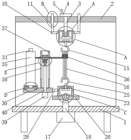
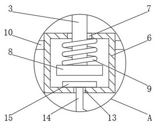
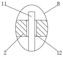
[0027] A wire binding device for electric power engineering, comprising a bottom plate 1 and a bracket 23, the upper end of the bottom plate 1 is welded with a frame 2, and the end of the frame 2 away from the bottom plate 1 is threadedly connected with a threaded rod 3, and the threaded rod 3 is away from One end of base plate 1 is welded with turntable 4, and the lower end of described base plate 1 is fixedly installed with motor 17, and described motor 17 is provided with rotating shaft 18, and described base plate 1 is connected with rotating shaft 18 in rotation, and the outside of described support 23 is welded with A connecting rod 29, the end of the connecting rod 29 is welded with a support plate 30, the support plate 30 is welded with a support shaft 31, and the outer side of the support shaft 31 is slidably sleeved with a support plate 32, on the support plate 30 A sleeve 37 is welded, and a sliding groove 38 is opened on the side wall of the sleeve 37 , and a bindin...


PUM


Abstract

The invention discloses a wire binding device for electric power engineering. The wire binding device for electric power engineering comprises a bottom plate and a support, a frame is welded to the upper end of the bottom plate, a threaded rod is connected to one end, away from the bottom plate, of the frame through threads, a rotating disc is welded to one end, away from the bottom plate, of the threaded rod, a motor is fixedly mounted at the lower end of the bottom plate, a rotating shaft is arranged on the motor, the rotating shaft is rotationally connected into the bottom plate, a connecting rod is welded to the outer side of the support, a supporting plate is welded to the tail end of the connecting rod, a supporting shaft is welded to the supporting plate, a supporting disc is slidably connected to the outer side of the supporting shaft in a sleeving mode, a sleeve is welded to the supporting plate, a sliding groove is formed in the side wall of the sleeve, and a binding wire is slidably connected in the sliding groove. The invention relates to the wire binding device for electric power engineering. The wire binding device has the characteristics of being high in wire binding packaging efficiency and uniform in material binding.

Description

technical field [0001] The invention belongs to the technical field of electric power engineering, in particular to a wire binding device for electric power engineering. Background technique [0002] Electric power engineering refers to engineering related to the production, transmission, and distribution of electric energy. In a broad sense, it also includes engineering that uses electricity as power and energy in various fields. At the same time, it can be understood that the power transmission and transformation industry expansion project. During the construction process of electric power engineering, the materials need to be bundled and transported with a wire binding device, including cables. [0003] In the prior art, when the wire binding device for electric power engineering is used, it is inconvenient to wire bind and package the materials, which makes the device wire binding and packaging efficiency low. At the same time, when the device binds the materials, the m...

Claims


Application Information

Patent Timeline
IPC IPC(8): B65B13/18B65B27/06
CPCB65B13/18B65B27/06
Inventor 孙业隆于波其他发明人请求不公开姓名
Owner STATE GRID SHANDONG ELECTRIC POWER CO LONGKOU POWER SUPPLY CO
Why Eureka
Try Eureka