Automatic lifting type stirring device

A stirring device and automatic lifting technology, which is applied to mixers with rotating stirring devices, mixer accessories, transportation and packaging, etc., can solve the problems of artificial tilting, the inability to accurately control the up and down movement of mixing blades, and the inability to ensure the uniformity of the material bucket Stirring and other issues

Pending Publication Date: 2021-05-18
湖北易信机械有限公司
View PDF0 Cites 0 Cited by
  • Summary
  • Abstract
  • Description
  • Claims
  • Application Information

AI Technical Summary

Problems solved by technology

[0002] During the construction process, materials such as cement and pigments need to be mixed with water before use. Artificial mixing cannot ensure uniform mixing wi

Method used


Image

  • Automatic lifting type stirring device

Examples


Example Embodiment

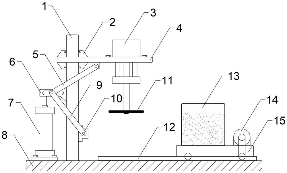
[0013] see figure 1 As shown, a kind of automatic lifting type stirring device comprises bottom plate 8, column 1, mixer 3, lifting plate 4, elevator 7 and first connecting rod 5, second connecting rod 9 and first slider 2, second slider 6, the third slide block 10, the column 1 and the second slide block 6 all have chute, the column 1 and the elevator 7 are installed vertically on the base 8, the first slide block 2, the second slide block 6, The third slider 10 is sequentially arranged in the chute of the column 1 from top to bottom, and the second slider 6 is also fixedly connected with the elevator 7. The lifting plate 4 is horizontally installed on the column 1 through the first slider 2, and the mixer 3 Installed on the front side of the lifting plate 4, one end of the first connecting rod 5 and the second connecting rod 9 are hinged in the chute of the second slider 6, and the other end of the first connecting rod 5 is hinged with the lower end surface of the lifting pl...


PUM


Abstract

The invention discloses an automatic lifting type stirring device. The device comprises a bottom plate, a stand column, a stirrer, a lifting plate, a lifter, a first connecting rod, a second connecting rod, a first sliding block, a second sliding block and a third sliding block. The stand column and the second sliding block are each provided with a sliding groove, the stand column and the lifter are vertically installed on a base. The first sliding block, the second sliding block and the third sliding block are sequentially arranged in the sliding groove of the stand column from top to bottom, the second sliding block is further fixedly connected with the lifter, the lifting plate is horizontally installed on the stand column through the first sliding block, the stirrer is installed on the front side of the lifting plate, and one end of the first connecting rod and one end of the second connecting rod are hinged into the sliding groove of the second sliding block. The other end of the first connecting rod is hinged to the lower end face of the lifting plate, and the other end of the second connecting rod is hinged to the third sliding block. The device has the advantages that through the structural design of the connecting rod and the sliding blocks, the lifting plate can ascend and descend in a horizontal state, and the stirrer and the lifting plate synchronously and vertically ascend and descend, so that a stirring area in the vertical direction is finely adjusted.

Description

technical field [0001] The invention relates to the technical field of stirring equipment, in particular to an automatic lifting stirring device. Background technique [0002] During the construction process, materials such as cement and pigments need to be mixed with water before use. Artificial mixing cannot ensure uniform mixing within the full depth of the material bucket, and the up and down movement of the mixing blades cannot be accurately controlled, and it is easy to cause artificial tilting. Contents of the invention [0003] The purpose of the present invention is to provide an automatic lifting stirring device in view of the existing technical status. Through the structural design of the connecting rod and the slider, the lifting plate can be lifted and lowered in a horizontal state, so that the mixer and the lifting plate are synchronously vertical Up and down, so as to fine-tune the mixing area in the vertical direction, the adjustment range is more accurate,...

Claims


Application Information

Patent Timeline
IPC IPC(8): B01F7/16B01F7/18B01F15/02
CPCB01F27/806B01F27/90B01F35/71B01F2101/28B01F2101/30
Inventor 易灿兵
Owner 湖北易信机械有限公司
Why Eureka
Try Eureka