
An optical positioning system

An optical positioning, six-axis technology, applied in the direction of using optical devices, instruments, measuring devices, etc., can solve the problems of inaccurate measurement results and the inability of testers to make adjustments in time, and achieve the effect of convenient operation

Active Publication Date: 2021-11-19
广州艾目易科技有限公司
View PDF4 Cites 2 Cited by
  • Summary
  • Abstract
  • Description
  • Claims
  • Application Information

AI Technical Summary

Problems solved by technology

However, the optical positioning system often produces tiny vibrations during measurement, and the existing optical positioning system cannot give vibration reminders in time, so the testers cannot make adjustments in time, further resulting in inaccurate measurement results

Method used


Image

  • An optical positioning system
  • An optical positioning system
  • An optical positioning system

Examples


Embodiment Construction

[0019] The following will clearly and completely describe the technical solutions in the embodiments of the present invention with reference to the accompanying drawings in the embodiments of the present invention. Obviously, the described embodiments are only some, not all, embodiments of the present invention. Based on the embodiments of the present invention, all other embodiments obtained by persons of ordinary skill in the art without creative efforts fall within the protection scope of the present invention.

[0020] It should be understood that the step numbers used herein are only for convenience of description, and are not intended to limit the execution order of the steps.

[0021] It should be understood that the terminology used in the description of the present invention is for the purpose of describing particular embodiments only and is not intended to limit the present invention. As used in this specification and the appended claims, the singular forms "a", "an"...


PUM


Abstract

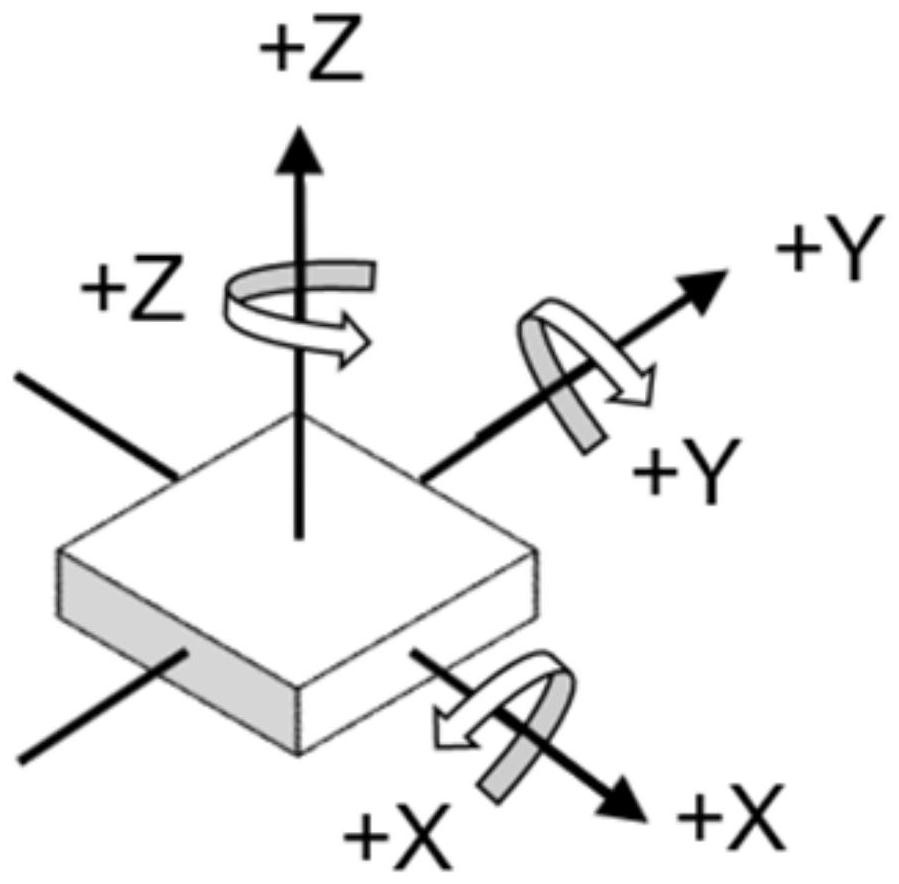
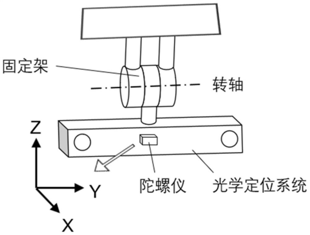
The invention discloses an optical positioning system, which comprises an image acquisition module, a control module, a six-axis gyroscope and a data display module; the image acquisition module and the data display module are respectively connected to the control module, and the six-axis gyroscope is arranged on the control module; The image acquisition module is used to collect the position information of the measured object, and generate the first data according to the position information; the six-axis gyroscope is used to collect the collision detection state information of the optical positioning system in real time, and generate the second data according to the collision detection state information. data; a control module, used to control the operation of the image acquisition module and the six-axis gyroscope, and transmit the received first data and second data to the data display module for display. The optical positioning system provided by the present invention can quickly determine the vibration of the optical positioning system and give a reminder, and at the same time can calculate the rotation and translation matrix of the changed pose relative to the original pose, and obtain accurate three-dimensional coordinate data to assist in measurement , easy to operate.

Description

technical field [0001] The invention relates to the technical field of optical positioning systems, in particular to an optical positioning system. Background technique [0002] The working principle of the optical positioning system is to transmit the detected three-dimensional coordinate information of the measured object to the host computer, and the subsequent processing of the host computer will display and interact with the three-dimensional coordinates. The three-dimensional coordinate information is relative to the optical positioning system. Therefore, the three-dimensional coordinate information measured by the optical positioning system is the most accurate only when the optical positioning system remains still. However, the optical positioning system often produces small vibrations during measurement, and the existing optical positioning system cannot give vibration reminders in time, so the testers cannot make adjustments in time, further resulting in inaccurate...

Claims


Application Information

Patent Timeline
Patent Type & Authority Patents(China)
IPC IPC(8): G01B11/00
CPCG01B11/002
Inventor 关沛峰王志刚薛富云李春田马家兴
Owner 广州艾目易科技有限公司
Learn More