
Method for extracting bolt hole characteristic data on basis of three-dimensional laser scanner

A technology of three-dimensional laser and characteristic data, applied in the direction of instruments, optical devices, measuring devices, etc., can solve the problems that the central coordinate data of bolt holes are difficult to be extracted accurately, the machining accuracy of components cannot be achieved, and the pre-assembly cannot be satisfied, etc., to achieve Guarantee the accuracy of test data, improve the measurement accuracy, and quickly calculate the effect

Active Publication Date: 2016-12-21
CCCC SECOND HARBOR ENG +2
View PDF7 Cites 14 Cited by
  • Summary
  • Abstract
  • Description
  • Claims
  • Application Information

AI Technical Summary

Problems solved by technology

For welded components, the allowable error is relatively large, and the test data can basically meet the requirements of virtual pre-assembly, but the bolt connection with high test accuracy cannot be effectively solved. The key problem is that the center coordinate data of the bolt hole is difficult to accurately extract. Conventional 3D laser scanning The instrument test technology directly scans the components, obtains a large number of component point cloud data, and directly fits the center coordinates of the bolt holes through the point cloud data. As a result, the central coordinate error of direct fitting is relatively large, which cannot meet the processing accuracy of the component itself, and cannot meet the requirements of pre-assembly. At the same time, a large amount of point cloud data software can automatically find the position of the characteristic bolt hole by mistake, and manual identification is required.

Method used


Image

  • Method for extracting bolt hole characteristic data on basis of three-dimensional laser scanner
  • Method for extracting bolt hole characteristic data on basis of three-dimensional laser scanner
  • Method for extracting bolt hole characteristic data on basis of three-dimensional laser scanner

Examples


Embodiment Construction

[0035] The present invention will be further described in detail below in conjunction with the accompanying drawings, so that those skilled in the art can implement it with reference to the description.

[0036] It should be noted that, in the description of the present invention, the terms "horizontal", "vertical", "upper", "lower", "front", "rear", "left", "right", "vertical", The orientation or positional relationship indicated by "horizontal", "top", "bottom", "inner", "outer", etc. is based on the orientation or positional relationship shown in the drawings, and is only for the convenience of describing the present invention and simplifying the description, and It is not to indicate or imply that the device or element referred to must have a particular orientation, be constructed in a particular orientation, or operate in a particular orientation, and thus should not be construed as limiting the invention.

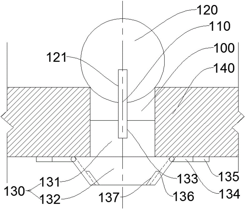
[0037] Such as figure 1 As shown, the present invention provide...


PUM


Abstract

The invention discloses a method for extracting the bolt hole characteristic data on the basis of a three-dimensional laser scanner and is used for measuring the characteristic data of a bolt hole on a steel structure. The method comprises steps that step 1, a radius and the height data of a to-be-measured bolt hole are measured, a spherical target is fixed in the to-be-measured bolt hole, and one end of the bolt hole contacts the spherical target; step 2, the three-dimensional laser scanner is utilized to carry out panorama scanning of the to-be-measured bolt hole and the spherical target, and the point cloud data of a surface of the spherical target is acquired; step 3, the point cloud data acquired in the step 2 is processed to acquire a three-dimensional coordinate of a center point of the spherical target, and a three-dimensional coordinate of a center point of the bolt hole can be acquired through calculation according to the three-dimensional coordinate of the center point of the spherical target. The method is advantaged in that the three-dimensional coordinate of the center point of the bolt hole is improved in an aspect of fitting precision compared with the traditional direct point cloud data, and thereby the reliable measurement data is provided for virtual pre-splicing of the steel structure realizing connection through a bolt.

Description

technical field [0001] The invention relates to the field of virtual pre-assembly of steel structures. More specifically, the present invention relates to a method for extracting bolt hole feature data based on a three-dimensional laser scanner. Background technique [0002] Steel components for bridges need to be pre-assembled after the factory is finished. In recent years, with the development of computer-aided manufacturing, more and more manufacturers have begun to study virtual pre-assembly to save a lot of manpower, material and financial resources. The first task of virtual pre-assembly is to collect the characteristic values ​​of real components, which is also the most critical task. The testing methods mainly include digital industrial measurement technology, 3D laser scanner testing technology, and laser tracker testing technology. For welded components, the allowable error is relatively large, and the test data can basically meet the requirements of virtual pre-a...

Claims


Application Information

Patent Timeline
Patent Type & Authority Applications(China)
IPC IPC(8): G01B11/00G01B11/08G01B11/06
CPCG01B11/002G01B11/0608G01B11/08
Inventor 项梁田唯朱浩李有为冯波翁方文曾炜
Owner CCCC SECOND HARBOR ENG
Learn More