Check patentability & draft patents in minutes with Patsnap Eureka AI!

Anti-rotation positioning structure for shaft

A positioning structure and anti-rotation technology, applied in the direction of shafts, shafts and bearings, mechanical equipment, etc., can solve the problems of unstable connection between the shaft and the sleeve, unstable shaft fixing, etc., and achieve the effect of stable connection and stable connection structure

Inactive Publication Date: 2021-05-28
无锡高润科技有限公司
View PDF0 Cites 0 Cited by
  • Summary
  • Abstract
  • Description
  • Claims
  • Application Information

AI Technical Summary

Problems solved by technology

[0003] Many existing shafts are rigidly plugged and fitted. After plugging and fitting between the bushing and the shaft, under high-strength torque, it will cause sliding between the bushing and the shaft as a whole, which will cause the overall shaft to be fixed unstable, or The connection relationship between the shaft and the sleeve is unstable

Method used


Image

  • Anti-rotation positioning structure for shaft
  • Anti-rotation positioning structure for shaft

Examples


Embodiment Construction

[0018] The following will clearly and completely describe the technical solutions in the embodiments of the present invention with reference to the accompanying drawings in the embodiments of the present invention. Obviously, the described embodiments are only some, not all, embodiments of the present invention.

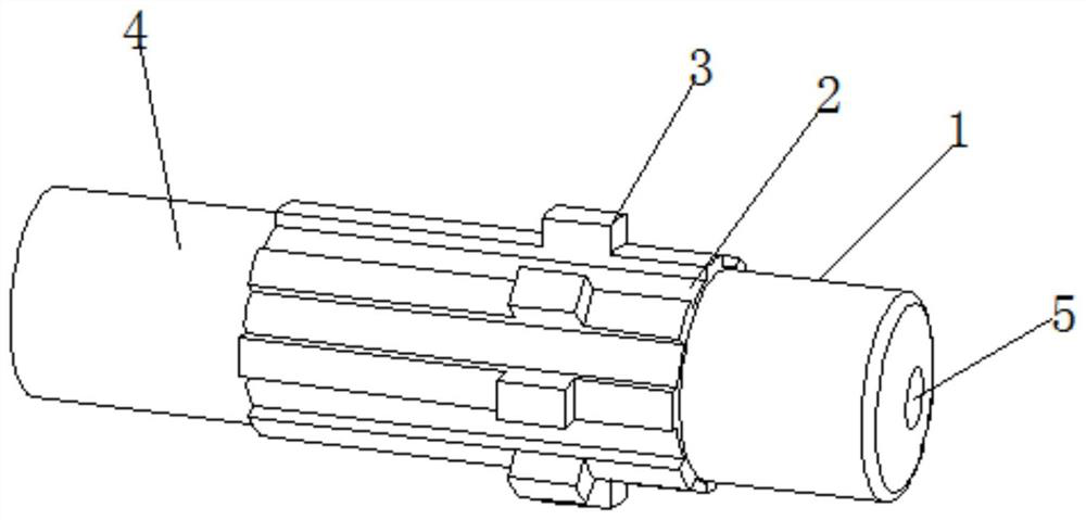
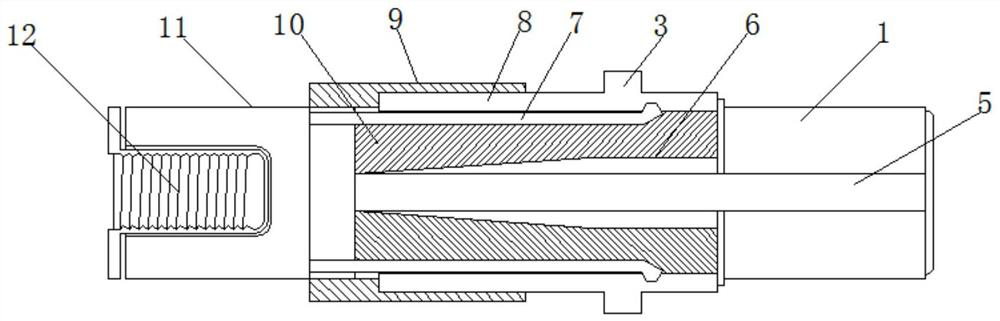
[0019] refer to Figure 1-2 , a shaft anti-rotation positioning structure, including a connecting shaft 1, one end of the connecting shaft 1 is integrally welded with a connecting sleeve 11, and the middle part of the inner wall of the connecting sleeve 11 is threadedly connected with an inner adjusting sleeve 12, and the connecting shaft 1 is close to the connecting sleeve 11 The outer wall of one end is equidistantly opened with a spline groove 8, and the inner wall of the spline groove 8 is clamped with an inner straight spline tooth 4, and the outer wall of the connecting shaft 1 close to the connecting sleeve 11 is clamped with a ferrule 9, and the ferrule 9 and ...


PUM


Abstract

The invention discloses an anti-rotation positioning structure for a shaft. The anti-rotation positioning structure comprises a connecting shaft, a connecting sleeve is integrally welded to one end of the connecting shaft, an inner adjusting sleeve is connected to the middle of the inner wall of the connecting sleeve through threads, spline grooves are formed in the outer wall of the end, close to the connecting sleeve, of the connecting shaft at equal intervals, inner linear spline teeth are clamped to the inner walls of the spline grooves, the outer wall of the side, close to the connecting sleeve, of the connecting shaft is connected with a clamping sleeve in a clamped mode, and the clamping sleeve is matched with the end of the inner linear spline teeth in a clamped mode. The inner linear spline teeth are annularly distributed on the outer wall of the connecting shaft at equal intervals, a concave-convex spline groove body is formed between the inner linear spline teeth and the outer wall of the connecting shaft to limit relative sliding between the shaft and a shaft sleeve, limiting teeth are arranged at the one-third position of the inner linear spline teeth, the limiting teeth limit relative sliding between the shaft sleeve and the shaft in the axial direction, an inner penetrating rod extrudes to enable a pressing rod and the inner side of the inner linear spline teeth to be mutually clamped, and it is guaranteed that the whole inner linear spline teeth are clamped in the groove body.

Description

technical field [0001] The invention relates to the technical field of shaft accessories, in particular to an anti-rotation positioning structure for a shaft. Background technique [0002] The shaft (shaft) is a cylindrical object that goes through the middle of the bearing or the middle of the wheel or the middle of the gear, but there are also a few of them that are square. A shaft is a mechanical part that supports and revolves with a rotating part to transmit motion, torque or bending moment. Generally, it is in the shape of a metal round rod, and each segment can have different diameters. The parts that make rotary motion in the machine are mounted on the shaft. [0003] Many existing shafts are rigidly plugged and fitted. After plugging and fitting between the bushing and the shaft, under high-strength torque, it will cause sliding between the bushing and the shaft as a whole, which will cause the overall shaft to be fixed unstable, or The connection between the sha...

Claims


Application Information

Patent Timeline
Patent Type & Authority Applications(China)
IPC IPC(8): F16C3/02
CPCF16C3/023
Inventor 黄善兴
Owner 无锡高润科技有限公司
Features
  • R&D
  • Intellectual Property
  • Life Sciences
  • Materials
  • Tech Scout
  • Unparalleled Data Quality
  • Higher Quality Content
  • 60% Fewer Hallucinations
Learn More