

High-tension combined trainer
A technology of trainers and pull rods, which is applied to muscle training equipment, gymnastics equipment, heavy objects, etc., can solve the problems of limiting the use cost and applicability of fitness equipment, the difficulty of adjusting the weight of fitness equipment, high cost and implementation cost, etc., to achieve overall High stability, increase the overall diversity, reduce the effect of falls
- Summary
- Abstract
- Description
- Claims
- Application Information
AI Technical Summary
Problems solved by technology
Method used
Image

Examples
Embodiment 1
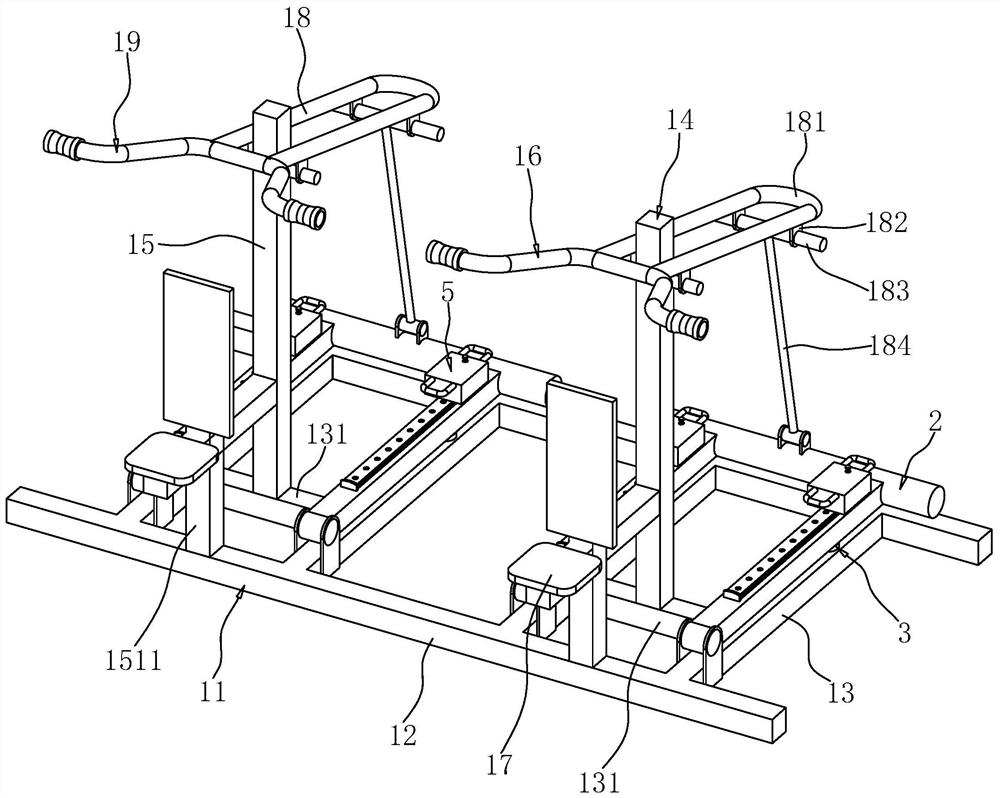
[0044] refer to figure 1 , a high-pull combined training device, including a support base 11 placed on the ground, the support base 11 includes two extension rods 12 arranged parallel to each other, and two pairs of support rods 13 are arranged in parallel between the two extension rods 12 , each group of supporting rods 13 is provided with a trainer body 14 .
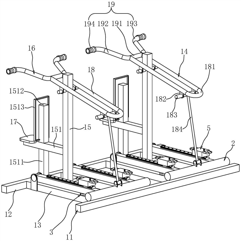
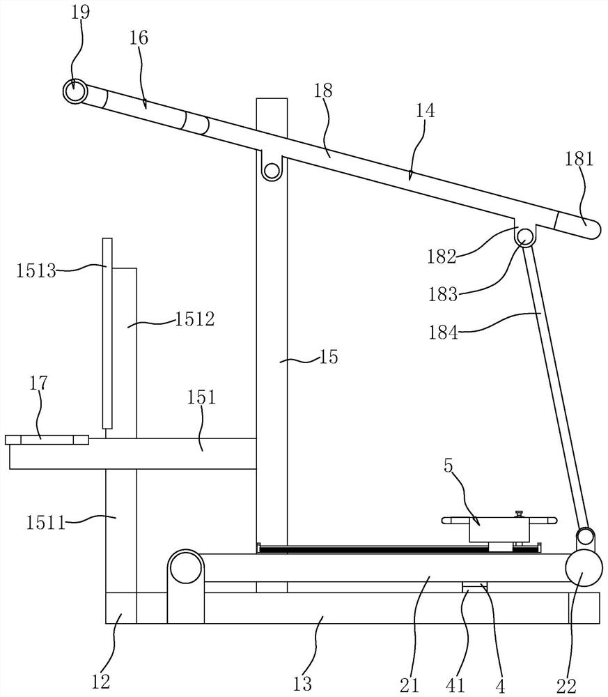
[0045] refer to figure 1 and figure 2 , the trainer body 14 includes a support portion 15 disposed between the supporting rods 13 of the same group and a training portion 16 disposed on the support portion 15 . Between the two supporting rods 13 of the same group, a fixed rod 131 is affixed, and the fixed rod 131 is vertically arranged with the supporting rod 13, and the distance between the fixed rod 131 and one of the extension rods 12 is 100% of the length of the supporting rod 13. One-third; the support part 15 is vertically arranged with the horizontal plane, and the end of the support part 15 towards the fixe...
Embodiment 2
[0056] A kind of high pull combination trainer, the difference with embodiment 1 is, as Figure 6 and Figure 7 As shown, the upper surface of the slider 52 defines an installation cavity 521 along the height direction of the slider 52 , and the location of the installation cavity 521 is located on one side of the slide rail 51 . The limit mechanism 6 includes a rack 66 fixed on the side of the slide rail 51 facing the installation cavity 521, the length of the rack 66 is the same as that of the slide rail 51; 521 communicate with each other through the communication groove 522, so that when the slider 52 and the slide rail 51 slide each other, the rack 66 will not interfere with the slider 52; shaft 67, and the bottom surface of the installation cavity 521 is provided with a limiting groove 523 for accommodating the lower end of the rotating shaft 67, and a pair of supporting springs 68 supporting the rotating shaft 67 are placed in the limiting groove 523; There is a drive...
PUM
 Abstract
Description
Claims
Application Information