Switch box
A switch box and self-resetting switch technology, applied in the field of switch boxes, can solve the problems of inconvenient operation of pulling the trigger, easy to squeeze the operator's palm, etc., and achieve the effects of low structural design precision requirements, easy grip, and smooth operation.
- Summary
- Abstract
- Description
- Claims
- Application Information
AI Technical Summary
Problems solved by technology
Method used
Image

Examples
Embodiment 1
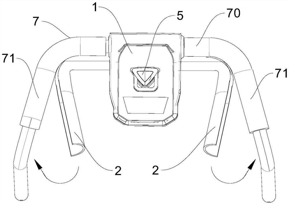
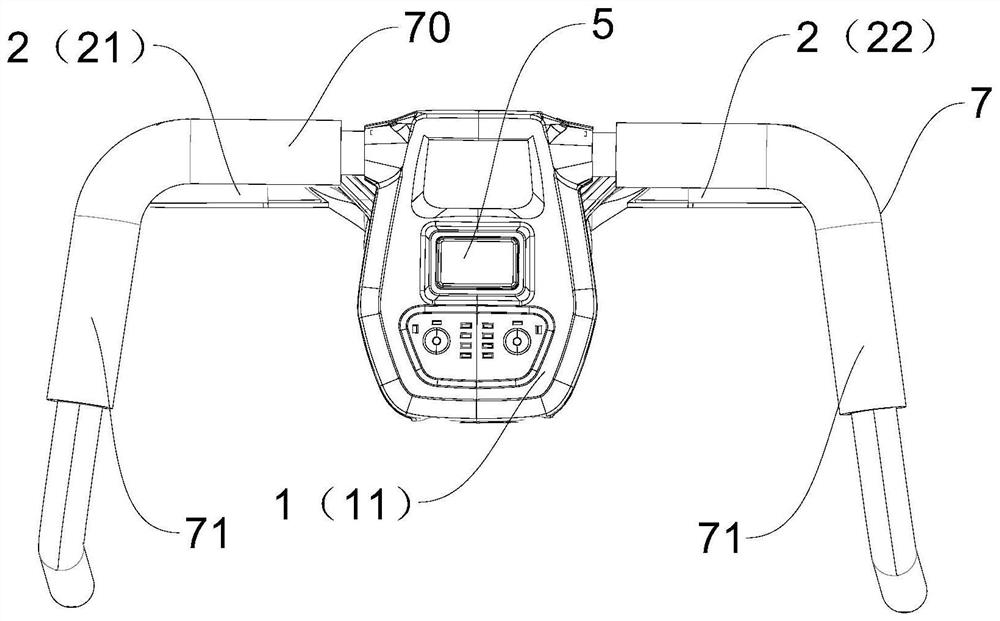
[0037] Embodiment one: if figure 2 As shown, a switch box includes a main box body 1 and a trigger 2 that is rotatably connected to the main box body 1. The main box body 1 includes an upper box body 11 and a lower box body 12 that are assembled together. The main box body 1 is installed on On the support section 70 of the handle 7, and the main box body 1 is located in the containing frame formed by the support section 70 and the armrest means 71 on both sides, that is, the main box body 1, the support section 70 and the armrest means 71 are roughly located on the same plane. In this embodiment, when the trigger 2 is pulled, the trigger 2 rotates from the side where the lower box body 12 is located to the side where the upper box body 11 is located. The "up" and "down" in the upper box body 11 and the lower box body 12 described in this embodiment represent the orientation, when the operator faces the main box body and grasps the handle with both hands, the box body near the...
Embodiment 2
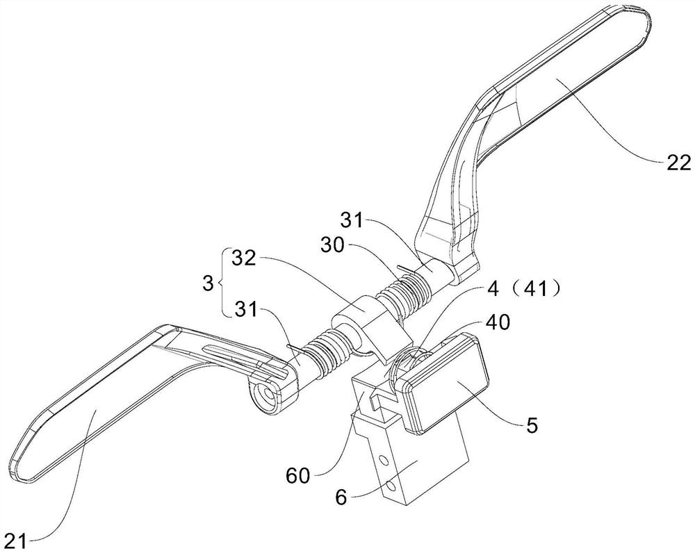
[0043] Embodiment two: if Figure 8 to Figure 11 As shown, this embodiment also provides a switch box. The difference between this embodiment and the above-mentioned embodiment is that the first transmission assembly 3 and the second transmission assembly 4 in this embodiment adopt different structures from those in the above-mentioned embodiment. . Specifically: in this embodiment, the first transmission assembly 3 includes a gear transmission assembly 33, a pressure block 34 and a pressure plate bracket 35, the trigger 2 is connected through the gear transmission assembly 33 and the pressure block 34, and the pressure plate support 35 includes a pressing plate 350 connected in sequence , L-shaped support plate 351, elastic plate 352 and cushion block 353, the pressing plate 350 is set close to the self-resetting switch 6, the pressing plate 350, the L-shaped supporting plate 351 and the elastic plate 352 form an accommodation cavity, and the pressing block 34 is partly locat...
PUM
 Abstract
Description
Claims
Application Information