Precise agriculture unmanned aerial vehicle with anti-collision function
A precision agriculture and unmanned aerial vehicle technology, applied in the direction of unmanned aircraft, fuselage, motor vehicles, etc., can solve the problems of easy breakage, space occupation, etc., to achieve convenient transportation, convenient installation and disassembly, and avoid internal structure stability Effect
- Summary
- Abstract
- Description
- Claims
- Application Information
AI Technical Summary
Problems solved by technology
Method used
Image
Examples
Embodiment 1
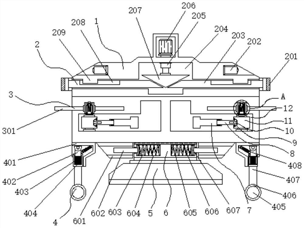
[0038] Example 1: See Figure 1-6 , a precision agricultural unmanned aerial vehicle with anti-collision function, including a housing 1 and a sprinkler 5, the bottom of the housing 1 is provided with a sprinkler 5, the top of the housing 1 is provided with a protective mechanism 2, the housing 1 The two ends of the sprayer 5 are provided with a disassembly structure 3, the bottom end of the housing 1 is provided with a buffer structure 4, the top of the sprinkler 5 is provided with a mounting structure 6, and the two ends of the housing 1 are provided with a storage structure;
[0039] see Figure 1-6 , a precision agricultural UAV with anti-collision function also includes a storage structure, the storage structure includes shrinkage grooves 12, the shrinkage grooves 12 are inlaid on both sides of the two ends of the shell 1, and one side of the shrinkage groove 12 is hinged with a wing One end of the rod 11 and the shrinkage groove 12 is inlaid with a placement groove 7, a...
Embodiment 2
[0042] Embodiment 2: the protective mechanism 2 is made up of anti-collision ring 201, distance sensor 202, movable rod 203, cavity 204, telescopic rod 205, cylinder 206, top plate 207, chute 208 and limit block 209, distance sensor 202 Fixedly connected to the top of both sides of the shell 1, the model of the distance sensor 202 is BX-LR1000N, the cavity 204 is set on the top of the inside of the shell 1, and the cylinder 206 is fixedly connected to the top of the shell 1, the cylinder 206 The model is SC200. The output end of the cylinder 206 runs through the top of the housing 1 and extends to the inside of the cavity 204. A telescopic rod 205 is fixedly connected to the bottom end of the telescopic rod 205. A top plate 207 is fixedly connected to the bottom of the cavity 204. A group of movable rods 203 are movably connected, and the top plate 207 is movably connected with the movable rods 203. The top of the movable rods 203 is inlaid with a chute 208, and the two sides o...
Embodiment 3
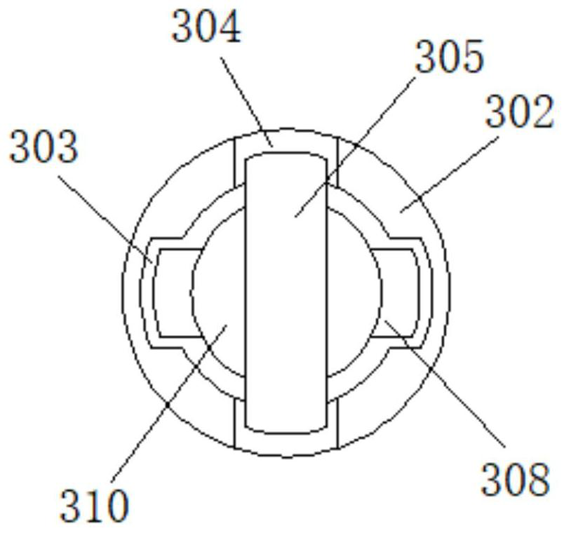
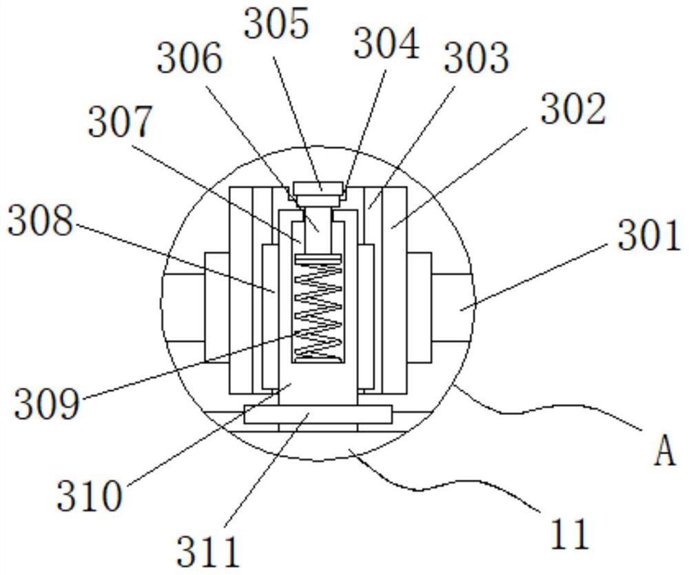
[0046] Embodiment 3: The disassembly structure 3 consists of a spiral wing 301, a sleeve 302, a limiting groove 303, a clamping groove 304, a clamping plate 305, a connecting rod 306, an empty groove 307, a limiting strip 308, a first spring 309, and a rotating shaft 310 Composed of a base plate 311, the rotating shaft 310 is fixedly connected to one end of the top of the wing bar 11, the bottom end of the rotating shaft 310 is fixedly connected to a base plate 311, and the outside of the rotating shaft 310 is movably connected to a sleeve 302, and the sleeve 302 is movably connected to the base plate 311. Both sides inside the sleeve 302 are inlaid with a set of limit grooves 303 respectively, and the two sides outside the rotating shaft 310 are fixedly connected with a set of limit bars 308 respectively. A plurality of sets of rotating shafts 310 are fixedly connected at intervals. The top of the rotating shafts 310 is inlaid with a hollow groove 307. The bottom end of the ho...
PUM
 Abstract
Description
Claims
Application Information
 - R&D
- Intellectual Property
- Life Sciences
- Materials
- Tech Scout
- Unparalleled Data Quality
- Higher Quality Content
- 60% Fewer Hallucinations
Browse by: Latest US Patents, China's latest patents, Technical Efficacy Thesaurus, Application Domain, Technology Topic, Popular Technical Reports.
© 2025 PatSnap. All rights reserved.Legal|Privacy policy|Modern Slavery Act Transparency Statement|Sitemap|About US| Contact US: help@patsnap.com


