Noise measurement and stabilization control method and system of ultra-short optical pulse amplification and compression system cep

A compression system and pulse amplification technology, applied in the field of ultrafast phenomena and precision measurement, can solve the problems of high pulse width and energy requirements, inability to adapt to high repetition frequency optical pulse carrier envelope phase single shot measurement, etc. Stable control of frequency bandwidth to achieve the effect of full frequency bandwidth measurement

Active Publication Date: 2022-05-10
XI'AN INST OF OPTICS & FINE MECHANICS - CHINESE ACAD OF SCI
View PDF0 Cites 0 Cited by
  • Summary
  • Abstract
  • Description
  • Claims
  • Application Information

AI Technical Summary

Problems solved by technology

[0008] The purpose of the present invention is to provide a simple and practical ultrashort optical pulse amplification and compression system CEP noise measurement method and system in order to address the above-mentioned deficiencies in the prior art. The complex method of bias frequency overcomes the fact that the existing interferometric spectrometry method cannot adapt to the single-shot measurement of the high repetition frequency optical pulse carrier envelope phase, and the CEP measurement method of the high-energy electron spectrum is only suitable for the CEP measurement of the few-period pulse, and the measurement The process requires high pulse width and energy

Method used


Image

  • Noise measurement and stabilization control method and system of ultra-short optical pulse amplification and compression system cep
  • Noise measurement and stabilization control method and system of ultra-short optical pulse amplification and compression system cep
  • Noise measurement and stabilization control method and system of ultra-short optical pulse amplification and compression system cep

Examples


Embodiment 1

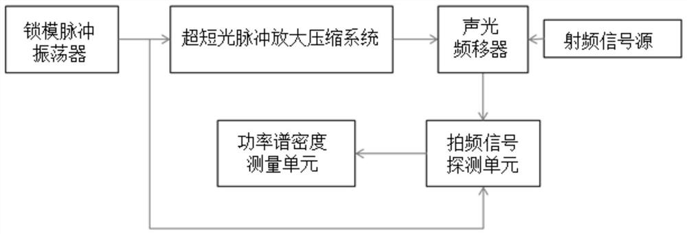
[0073] This embodiment provides a CEP noise measurement system of an ultrashort optical pulse amplification and compression system, such as figure 2 As shown, the measured ultrashort optical pulse amplification and compression system is a general-purpose chirped pulse amplification system, and the chirped pulse amplification system includes a pulse stretcher, an amplifier, and a pulse compressor;

[0074] The measurement system includes a seed pulse source, a beam splitter, an acousto-optic frequency shift unit, a beat frequency signal detection unit and a power spectral density measurement unit;

[0075] Wherein, the acousto-optic frequency shift unit includes an acousto-optic frequency shifter and a radio frequency signal source that applies a frequency stabilization signal to the acousto-optic frequency shifter;

[0076] The seed light emitted by the seed pulse source (this embodiment adopts a mode-locked pulse oscillator) is divided into two beams of light by a beam split...

Embodiment 2

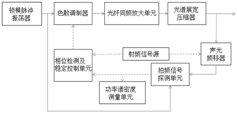
[0087] In order to realize the stable control of the carrier envelope phase CEP of the ultrashort optical pulse amplification and compression system, this embodiment provides a stable control system for the ultrashort optical pulse amplification and compression system CEP, such as image 3 As shown, the measured ultrashort optical pulse amplification and compression system includes an optical fiber same-frequency amplification unit and a spectrum stretching compressor;

[0088] The stable control system includes a bias frequency stable mode-locked fiber oscillator, a first beam splitter, an electro-optic dispersion modulator, a second beam splitter, an acousto-optic frequency shift unit, a beat frequency signal detection unit, and a power spectral density measurement unit, Phase detection and stabilization unit;

[0089] The acousto-optic frequency shift unit includes an acousto-optic frequency shifter and a radio frequency signal source that applies a frequency stabilization ...

Embodiment 3

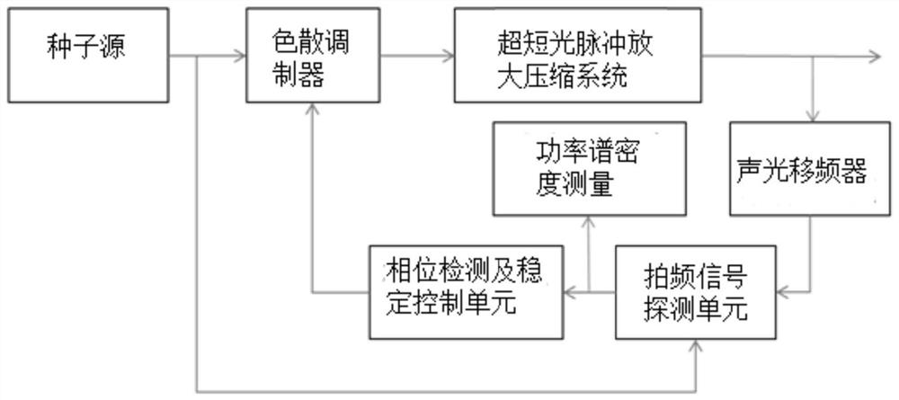
[0105] This embodiment provides a CEP stability control system for an ultrashort optical pulse amplification and compression system, such as Figure 4 As shown, the measured ultrashort optical pulse amplification and compression system includes a pulse stretcher, a frequency reduction amplification unit and a pulse compressor arranged sequentially along the optical path;

[0106] The stable control system includes a bias frequency stable Ti:sapphire oscillator, a third beam splitter, an electro-optical dispersion modulator, a fourth beam splitter, an acousto-optic frequency shift unit, a beat frequency signal detection unit, a power spectral density measurement unit, and a phase Detection and stabilization unit;

[0107] The acousto-optic frequency shift unit includes an acousto-optic frequency shifter and a radio frequency signal source that applies a frequency stabilization signal to the acousto-optic frequency shifter (in this embodiment, the radio frequency signal source a...


PUM


Abstract

The invention discloses a method and system for noise measurement and stable control of an ultra-short optical pulse amplification and compression system CEP. Optical frequency shift; the frequency shift of optical frequency shift comes from a stable radio frequency signal applied externally, thereby generating a signal light with an additional bias frequency relative to the bias frequency of the seed light; the signal light carrying the additional bias frequency and the seed The beat frequency signal is obtained by light beat frequency; the noise spectrum of the CEP noise signal generated by the ultrashort optical pulse amplification and compression system can be obtained by measuring the power spectral density of the beat frequency signal; the beat frequency signal is phase-compared with the radio frequency signal to obtain Phase detection signal; the phase detection signal is fed back to the photoelectric dispersion modulator through phase-locked amplification to realize the stable control of the full frequency bandwidth of the amplification and compression system CEP. The implementation process of the invention is simple and practical, and is applicable to various forms of ultrashort optical pulse amplification and compression systems.

Description

technical field [0001] The invention belongs to the technical field of ultrafast phenomena and precision measurement, and in particular relates to a simple and practical ultrashort optical pulse amplification and compression system CEP noise measurement and stability control method and system. Background technique [0002] At present, research in the field of optics in the field of optical frequency scales and ultrafast phenomena has reached 10-18 frequency standard precision and 10-18 second time precision. The main contribution to both comes from the generation of ultrashort optical pulses. [0003] The absolute frequency of the optical frequency marker f=f ceo +nf r The improvement of standard precision is strongly dependent on the repetition rate f of the optical frequency comb with ultrashort optical pulses r and bias frequency f ceo stability. The study of the interaction between light and matter under extreme conditions, especially the study of deeper high-order ...

Claims


Application Information

Patent Timeline
Patent Type & Authority Patents(China)
IPC IPC(8): G01J1/42G01J11/00
CPCG01J1/42G01J11/00G01J2001/4238
Inventor 王屹山程昭赵卫王向林
Owner XI'AN INST OF OPTICS & FINE MECHANICS - CHINESE ACAD OF SCI
Why Eureka
Try Eureka