
Rotor core, motor rotor, motor

A rotor core and iron core technology, which is applied in the field of motors, rotor cores, and motor rotors, can solve problems such as magnetic flux leakage and large torque ripple, and achieve the effects of eliminating harmonics, reducing torque ripple and cogging torque Effect

Active Publication Date: 2022-04-01
GREE ELECTRIC APPLIANCES INC
View PDF8 Cites 0 Cited by
  • Summary
  • Abstract
  • Description
  • Claims
  • Application Information

AI Technical Summary

Problems solved by technology

[0003] For ferrite permanent magnet auxiliary motors, since the remanence and coercive force of ferrite are lower than those of rare earth permanent magnets, in order to ensure the overall output torque of the motor, double-layer or multi-layer permanent magnets are often used. There is a magnetic bridge between the outer circles of the rotor. During the actual operation, the magnetic bridge is partially saturated, resulting in magnetic flux leakage and large torque ripple.

Method used


Image

  • Rotor core, motor rotor, motor
  • Rotor core, motor rotor, motor
  • Rotor core, motor rotor, motor

Examples


Embodiment Construction

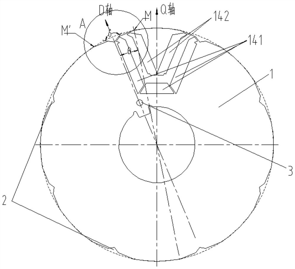
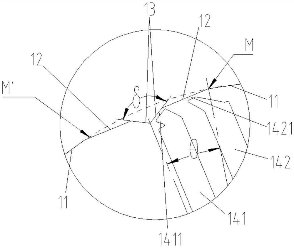
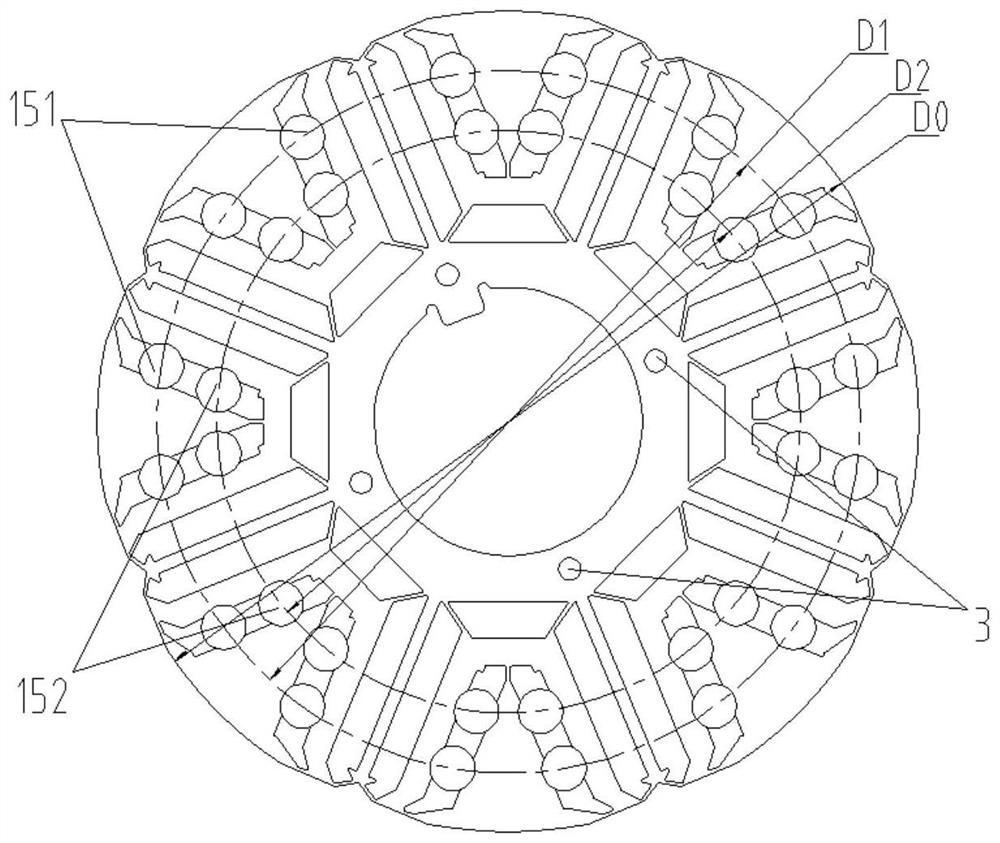
[0031] see in conjunction Figure 1 to Figure 8 As shown, according to the embodiment of the present invention, a rotor core is provided, which includes a core body 1, the core body 1 has a plurality of magnetic poles that alternate evenly along its circumferential direction, and any two adjacent magnetic poles are about D Axisymmetric, on any radial surface of the iron core body 1, in the same magnetic pole, the outer peripheral wall of the iron core body 1 has a circular arc symmetrical about the Q axis (the axis of symmetry of each magnetic pole) segment 11 and the trimming straight segment 12 at both ends of the arc segment 11, the length of the line between any point on the trimming straight segment 12 and the axis of the iron core body 1 is shorter than the arc The length of the line between any point on the segment 11 and the axis of the iron core body 1 . In this technical solution, by replacing the outer circular arc of the rotor iron core with a straight line trimmi...


PUM


Abstract

The invention provides a rotor core, a motor rotor, and a motor, wherein the rotor core includes a core body, the core body has a plurality of magnetic poles that alternate uniformly along its circumferential direction, and any two adjacent magnetic poles are about D Axisymmetric, on any radial surface of the iron core body, in the same magnetic pole, the outer peripheral wall of the iron core body has a circular arc segment symmetrical to the Q axis and trimming edges at both ends of the circular arc segment A straight line segment, the length of the line between any point on the trimmed straight line segment and the axis of the iron core body is shorter than the length of the line between any point on the arc segment and the axis of the iron core body . According to the present invention, by replacing the outer circular arc of the rotor iron core with a straight line trimming section near the D axis, the air gap of the stator and rotor can be changed, the magnetic density of the D and Q axis air gaps can be optimized, and the torque ripple can be reduced.

Description

technical field [0001] The invention belongs to the technical field of motor manufacturing, and in particular relates to a rotor iron core, a motor rotor and a motor. Background technique [0002] Permanent magnet assisted synchronous reluctance motor has become a hotspot in the field of motor research due to its small size, light weight, high efficiency, and high power density. Its output torque consists of two parts: reluctance torque and permanent magnet torque. [0003] For ferrite permanent magnet auxiliary motors, since the remanence and coercive force of ferrite are lower than those of rare earth permanent magnets, in order to ensure the overall output torque of the motor, double-layer or multi-layer permanent magnets are often used. There is a magnetic bridge between the outer circles of the rotor. During the actual operation, the magnetic bridge is partially saturated, resulting in magnetic flux leakage and large torque ripple. Contents of the invention [0004] ...

Claims


Application Information

Patent Timeline
Patent Type & Authority Patents(China)
IPC IPC(8): H02K1/276H02K1/28H02K21/02
CPCH02K1/27H02K1/28H02K21/028H02K2213/03
Inventor 王勇陈彬童童廖克亮张健黎永材
Owner GREE ELECTRIC APPLIANCES INC
Learn More