An integrated soil thermal desorption device with internal and external heating

A technology of internal and external heating and soil heating, applied in the field of contaminated soil remediation, can solve problems such as low thermal desorption efficiency, and achieve the effects of increasing unit processing capacity, increasing heat transfer area, and increasing heating rate

CN112934941BActive Publication Date: 2022-06-07SOUTHEAST UNIV
10 Cites 0 Cited by

Patent Information

Authority / Receiving Office
CN · China
Patent Type
Patents(China)
Current Assignee / Owner
Publication Date
2022-06-07

Smart Images

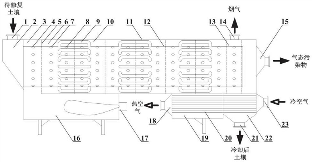
  • Figure 1
    Figure 1
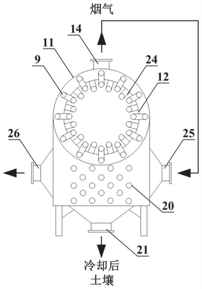
  • Figure 2
    Figure 2
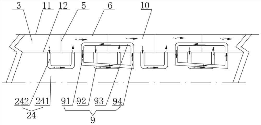
  • Figure 3
    Figure 3
Patent Text Reader

Abstract

The invention relates to an internal and external heating integrated soil heat desorption device, which comprises an inner cylinder for transporting soil in the axial direction and an outer casing arranged outside the inner cylinder, a cavity is formed between the outer wall of the inner cylinder and the inner wall of the outer casing, and the inside of the cavity is There are multiple partitions in the axial direction, and the partitions divide the cavity in the axial direction into primary distribution boxes, secondary distribution boxes, tertiary distribution boxes... the final distribution box; the primary distribution box communicates with the combustion flue gas , between two adjacent distribution boxes, a number of communication pipes are used to realize the communication of smoke gas. The smoke inlet and outlet of each communication pipe are respectively located on the inner cylinder wall corresponding to the two adjacent distribution boxes, and the communication pipe is located inside the inner cylinder. , so that the flue gas enters the next-level distribution box from the upper-level distribution box through the Unicom pipe in a serpentine path, and finally reaches the final-level distribution box. The invention adopts the method of simultaneously heating the inside and outside of the soil, which greatly increases the heating rate of the soil, and can significantly increase the unit processing capacity of the thermal desorption device.
Need to check novelty before this filing date? Find Prior Art

Description

technical field

[0001] The invention relates to the technical field of contaminated soil remediation, in particular to a soil thermal desorption device integrating internal and external heating. Background technique

[0002] At present, organic contaminated soil remediation technologies are mainly divided into three categories: physical remediation, chemical remediation and bioremediation, as well as combined remediation technologies based on the above technologies. Among them, thermal desorption remediation technology is one of the most effective methods of ex-situ desorption. It uses the method of heating the contaminated soil to volatilize the organic pollutants in it. It has the advantages of high pollutant removal efficiency, short remediation period, wide application range and technological The principle is simple and so on.

[0003] The existing thermal desorption device usually adopts an external heat rotary kiln structure, and the heating device is arranged outside...

Examples

Embodiment Construction

[0031] The specific embodiments of the present invention will be described below with reference to the accompanying drawings.

[0032] like figure 1 As shown, the soil thermal desorption device with integrated internal and external heating in this embodiment includes an inner cylinder 12 for conveying soil in the axial direction and an outer casing 11 arranged outside the inner cylinder 12. A cavity for the circulation of flue gas is formed, and a plurality of partitions 5 are arranged in the cavity along the axial direction. Box 10... The final stage distribution box; the primary distribution box 3 is communicated with the combustion flue gas, and the flue gas is communicated between two adjacent distribution boxes through a plurality of communication pipes 24, and the smoke inlet and smoke outlet of each communication tube 24 are respectively It is located on the wall of the inner cylinder 12 corresponding to the two adjacent distribution boxes, and the communication pipe 2...