An electrical distribution switch cabinet
A power distribution switch, electrical technology, applied in substation/distribution device housing, substation/switch layout details, electrical components, etc. question
- Summary
- Abstract
- Description
- Claims
- Application Information
AI Technical Summary
Problems solved by technology
Method used
Image
Examples
Embodiment 1
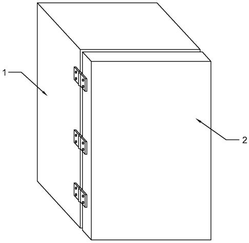
[0031] Such as figure 1 As shown, in the embodiment of the present invention, the electrical distribution switch cabinet includes:
[0032] Cabinet body 1, a cabinet door 2 is connected to one side of the cabinet body 1, and the connection mode between the cabinet body 1 and the cabinet door 2 can be a hinge connection, or other connection modes, which will not be repeated here;
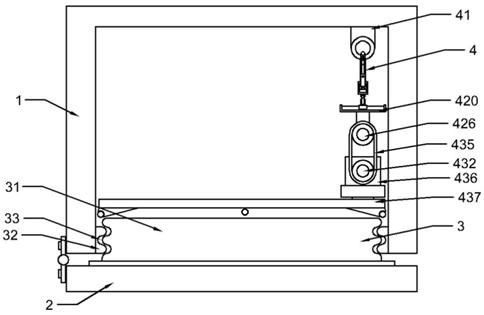
[0033] The sealing structure 3 is arranged on the cabinet body 1 and the cabinet door 2, and is used to realize the complete sealing of the cabinet body 1 and prevent water from flowing into the cabinet body 1. The sealing structure 3 is a soft colloidal solid, wherein Rubber products are preferred;
[0034] The detection device 4 is fixedly installed inside the cabinet body 1, and is used to detect the sealing performance of the sealing structure 3, so as to prevent a large amount of water from entering the cabinet body 1 due to failure to detect the sealing problem of the sealing structure 3 in ti...
Embodiment 2
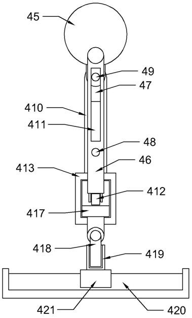
[0046] Such as Figure 2 to Figure 10 As shown, in the embodiment of the present invention, the detection device 4 also includes:
[0047] The first support member 41 is fixedly installed on the inner wall of the cabinet body 1;
[0048] The first motor 42 is fixedly installed on the first support member 41, and the output end of the first motor 42 is connected to the swing assembly;
[0049] The second support member 43 is fixedly installed on the inner wall of the cabinet body 1;
[0050] The second motor 44 is fixedly installed on the second support member 43 , and the output end of the second motor 44 is connected with the commutation assembly.
[0051]Wherein, the first support member 41 and the second support member 43 can be a rod-shaped structure, and can also be a plate-shaped structure; the structure of the first motor 42 and the second motor 44 is not limited to a rotary motor or a rotary motor, and everything can be driven to rotate Any component can be used, so...
Embodiment 3
[0086] Such as Figure 2 to Figure 10 As shown, in the embodiment of the present invention, the detection component includes:
[0087] The threaded part 432 is rotatably connected with the inner wall of the cabinet body 1;
[0088] The first rotating member 433 and the second rotating member 434 are fixedly installed on the rotating member 426 and the screw member 432, and a linkage belt 435 is arranged between the first rotating member 433 and the second rotating member 434 , for transmitting the rotation of the rotating member 426 to the screw member 432, so that the screw member 432 can drive the detection assembly up and down;
[0089] The threaded block 436 is sleeved on the threaded member 432, and is used to receive the rotation of the threaded member 432 and convert it into a lifting motion;
[0090] The water flow detection module 437 is fixedly connected with the threaded block 436 and is used to detect whether there is water flow into the position where the cabine...
PUM
 Abstract
Description
Claims
Application Information
 - R&D
- Intellectual Property
- Life Sciences
- Materials
- Tech Scout
- Unparalleled Data Quality
- Higher Quality Content
- 60% Fewer Hallucinations
Browse by: Latest US Patents, China's latest patents, Technical Efficacy Thesaurus, Application Domain, Technology Topic, Popular Technical Reports.
© 2025 PatSnap. All rights reserved.Legal|Privacy policy|Modern Slavery Act Transparency Statement|Sitemap|About US| Contact US: help@patsnap.com


