Steering oil tank and machining process thereof

A processing technology and oil tank technology, applied in the direction of fluid steering mechanism, oil supply tank device, fluid pressure actuating device, etc., can solve the problems of hydraulic oil splashing, affecting the working performance of steering oil tank, etc., to ensure the stability of the effect. Effect

Pending Publication Date: 2019-06-14
武汉金达利科技有限公司
View PDF1 Cites 1 Cited by
  • Summary
  • Abstract
  • Description
  • Claims
  • Application Information

AI Technical Summary

Problems solved by technology

[0004] The above-mentioned existing technical solutions have the following defects: the multi-layer circular gas-liquid separation plate ensures a good sealing effect between the tank body and the tank cover, and the oil molecules return to the tank body, but in the process of long-term heat generation and shaking After that, the hydraulic oil in the tank splashes out, affecting the normal working performance of the steering oil tank

Method used


Image

  • Steering oil tank and machining process thereof
  • Steering oil tank and machining process thereof
  • Steering oil tank and machining process thereof

Examples


Embodiment 1

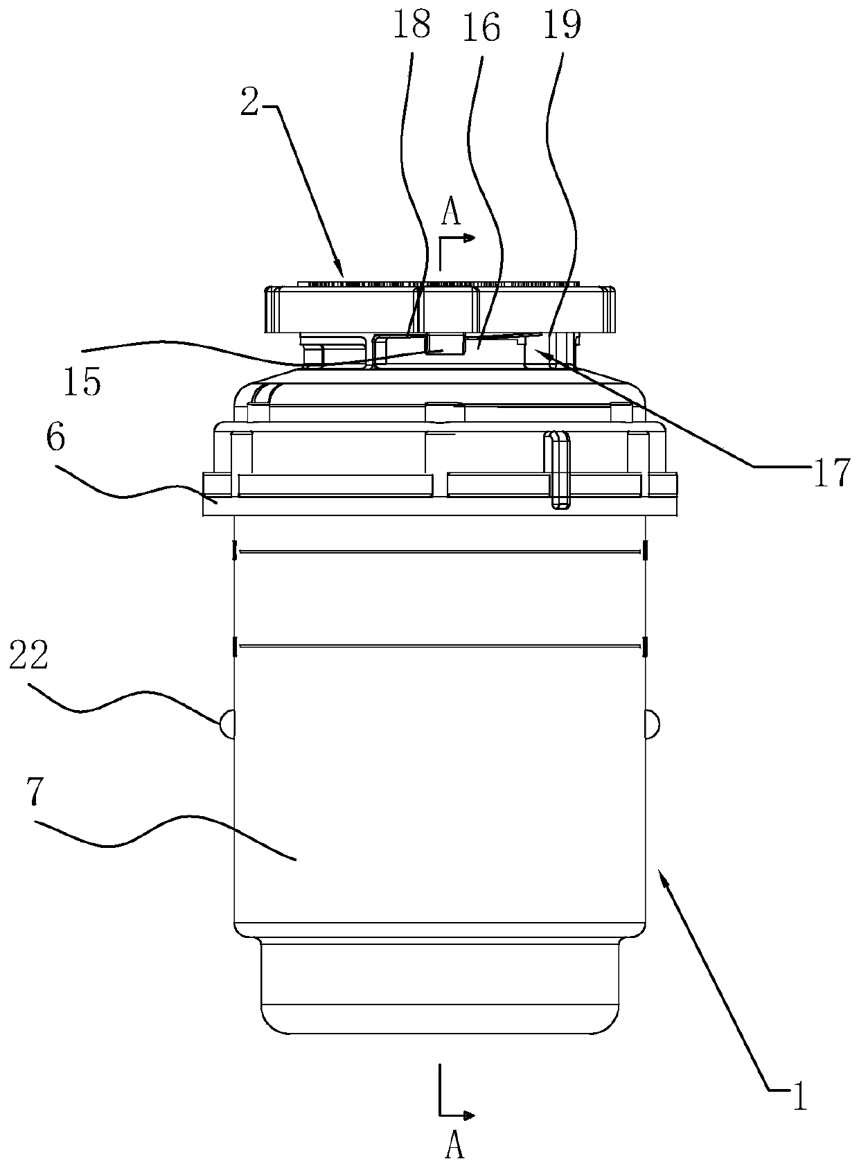
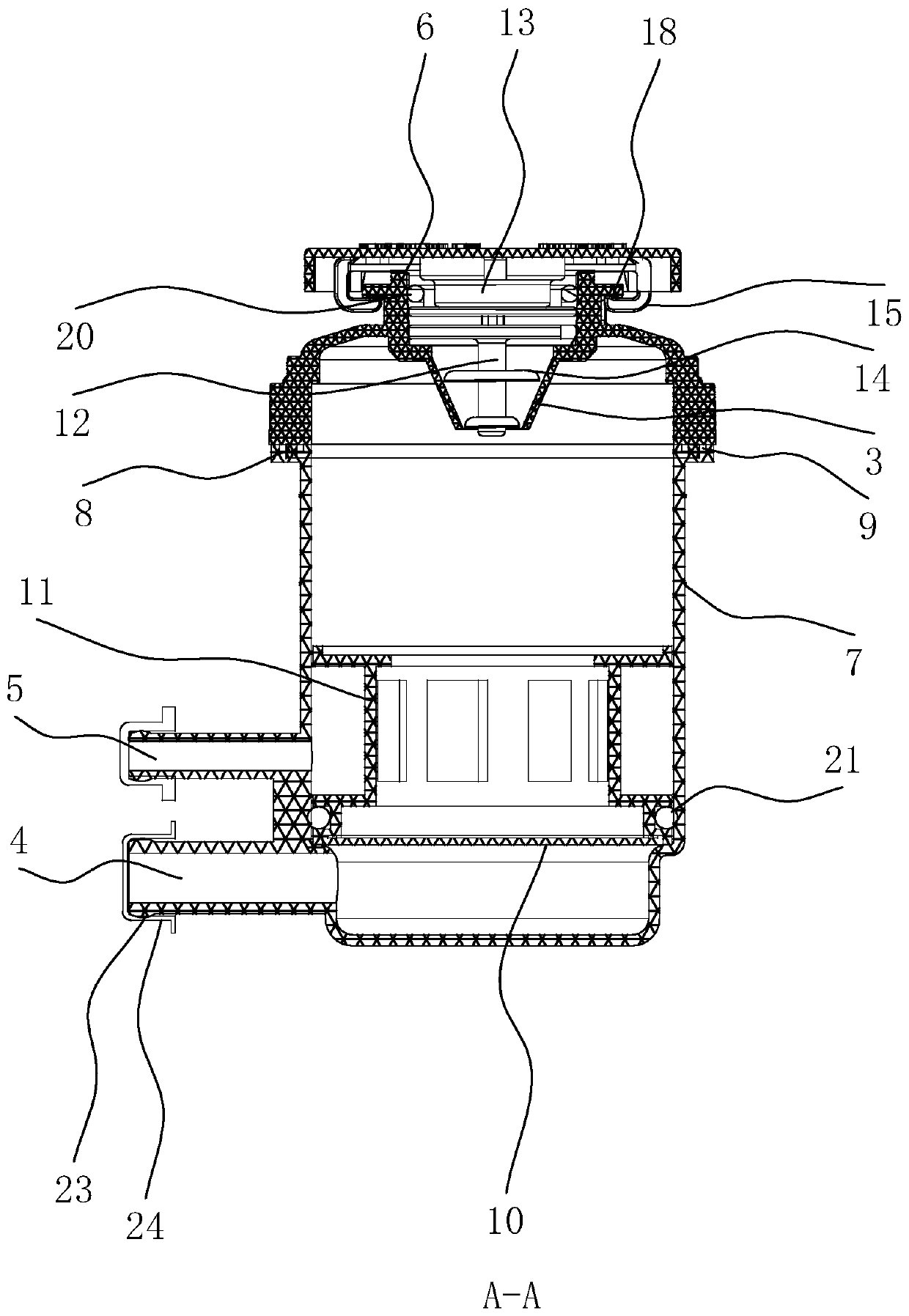
[0044] refer to figure 1 and figure 2 , is a steering oil tank disclosed by the present invention, comprising a tank body 1 and a tank cover 2, the tank body 1 is provided with an oil tank mouth 3, an oil inlet 4 and an oil outlet 5, and the engine oil is added through the oil tank mouth 3 Into the tank 1, the engine oil in the tank 1 provides power to the truck through the oil outlet 5, and the engine oil flows back into the tank 1 through the oil inlet 4. When the engine oil works in the tank 1 for a long time, it will vibrate and generate heat. The engine oil will flow out from the connection between the tank body 1 and the tank cover 2, which will affect the normal power supply effect of the steering oil tank to the truck. In order to ensure the sealing effect between the tank body 1 and the tank cover 2, the tank body 1 includes the upper tank body 6 and the lower tank body 7. The can lid 2 includes an abutment portion and a protective portion 13, and the abutment porti...

Embodiment 2

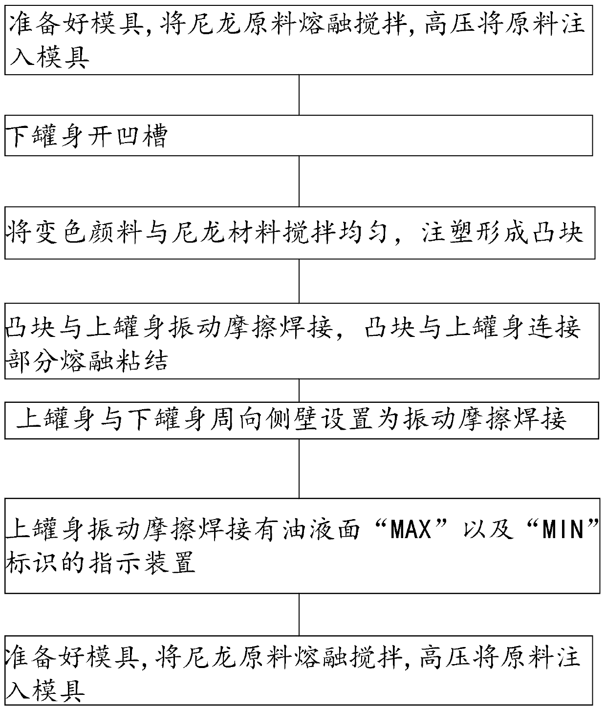
[0050] refer to figure 1 and image 3 , a kind of processing technology that turns to oil tank, comprises the steps:

[0051] Step 1: Prepare the mold, melt and stir the nylon raw material, and inject the raw material into the model under high pressure;

[0052] Step 2, groove the lower tank body (9);

[0053] Step 3, mix the color-changing pigment and nylon material evenly, and inject to form bumps (8),

[0054] Step 4, the bump (8) and the upper tank body (6) are vibration-friction welded, and the connection part between the bump (8) and the upper tank body (6) is fused and bonded;

[0055] Step five, setting the circumferential side walls of the upper tank body (6) and the lower tank body (7) as vibration friction welding;

[0056] Step 6, the upper tank body (6) is vibrated and friction-welded with the indicating device marked with the oil level "MAX" and "MIN";

[0057] Step seven, ultrasonic welding is carried out between the protective part (13) and the abutment pl...


PUM


Abstract

The invention discloses a steering oil tank and a machining process thereof. The steering oil tank comprises a tank body and a tank cover, wherein the tank body is provided with an oil tank mouth, anoil inlet and an oil outlet and comprises an upper tank body and a lower tank body, the upper tank body is provided with a convex block, the lower tank body is provided with a groove, the convex blockis connected inside the groove in an inserted manner, the lower tank body is internally provided with a filter portion, the filter portion comprises a bottom filter net and a circumferential filter net, the oil outlet is located inside a space enclosed by the circumferential filter net and the lower tank body, the oil tank mouth is arranged in a hopper shape, the tank cover comprises an abutted connection portion and a protective portion, the abutted connection portion is provided with an insert connection column and a plurality of sets of abutted connection plates, the centers of the abuttedconnection plates are located on the insert connection column, the protective portion is provided with a plurality of sets of clamping buckles, the upper tank body is provided with a plurality of sets of clamping grooves, and the clamping buckles and the clamping grooves are connected with clamping connection components in a clamped manner. By means of the technical field of the steering oil tankand the machining process thereof, the sealing effect between the tank body and the tank cover is guaranteed, machine oil inside the steering oil tank is guaranteed to work normally, and the machineoil work efficiency is improved.

Description

technical field [0001] The invention relates to the technical field of automobile steering power equipment, in particular to a steering oil tank and its processing technology. Background technique [0002] The existing hydraulic power steering system for light trucks usually includes a steering oil tank, a steering gear and a power steering oil pump. The steering oil tank is used to provide hydraulic oil to the steering gear and power steering oil pump. , When the vehicle is driving on a bumpy road for a long time, due to the high compressibility of the gas, it will cause a series of abnormal phenomena such as impact, noise, and heat of the actuator, and the steering oil in the steering oil tank will seep out of the oil tank. The amount of oil in the oil tank is reduced, and the outer surface of the steering oil tank is covered with oil, which affects the cleanliness and appearance, and has a serious impact on the working performance of the steering system. [0003] In resp...

Claims


Application Information

Patent Timeline
Patent Type & Authority Applications(China)
IPC IPC(8): F15B1/26F15B21/041B62D5/06B29C69/00
Inventor 郑斌高吭陶海波陈翱翔
Owner 武汉金达利科技有限公司
Why Eureka
Try Eureka