Sliding part

A technology of sliding parts and sliding surfaces, which is applied in the direction of engine components, engine seals, mechanical equipment, etc., can solve the problems of increased leakage, increased torque, and increased torque, and achieve the effect of both sealing and lubrication and preventing leakage

Active Publication Date: 2015-02-04
EAGLE INDS
View PDF11 Cites 15 Cited by
  • Summary
  • Abstract
  • Description
  • Claims
  • Application Information

AI Technical Summary

Problems solved by technology

[0005] However, in the invention described in the above-mentioned Patent Document 1, when there is a pressure difference between the inner and outer peripheries of the sliding surface of the seal, etc., it is necessary to overcome the suction effect of the pressure, and there is a problem that the fluid cannot be drawn back due to the magnitude of the pressure. in the case of
Therefore, when the pressure difference is small, leakage can be prevented, but there is a problem that the leakage amount increases when the pressure difference is large.
In addition, in the invention described in the above-mentioned Patent Document 2, if the suction effect of the dimple portion on the side of the sealed fluid is too strong, the amount of leakage increases. Conversely, if the suction effect of the dimple portion on the air side is too strong , the fluid to be sealed disappears from the sealing surface, and the following phenomenon occurs: These dimples formed on the sealing surface directly contact the sliding surface on the other side, resulting in an increase in torque
In prior art 2, there is a problem that in order to prevent an increase in leakage and an increase in torque, it is necessary to balance the suction effects of the respective dimples, but this is actually quite difficult

Method used


Image

  • Sliding part
  • Sliding part
  • Sliding part

Examples


Embodiment 1

[0065] refer to Figure 1 to Figure 3 , the sliding member of Embodiment 1 of the present invention will be described.

[0066] In addition, in this embodiment, a case where the member constituting the mechanical seal is a sliding member will be described as an example.

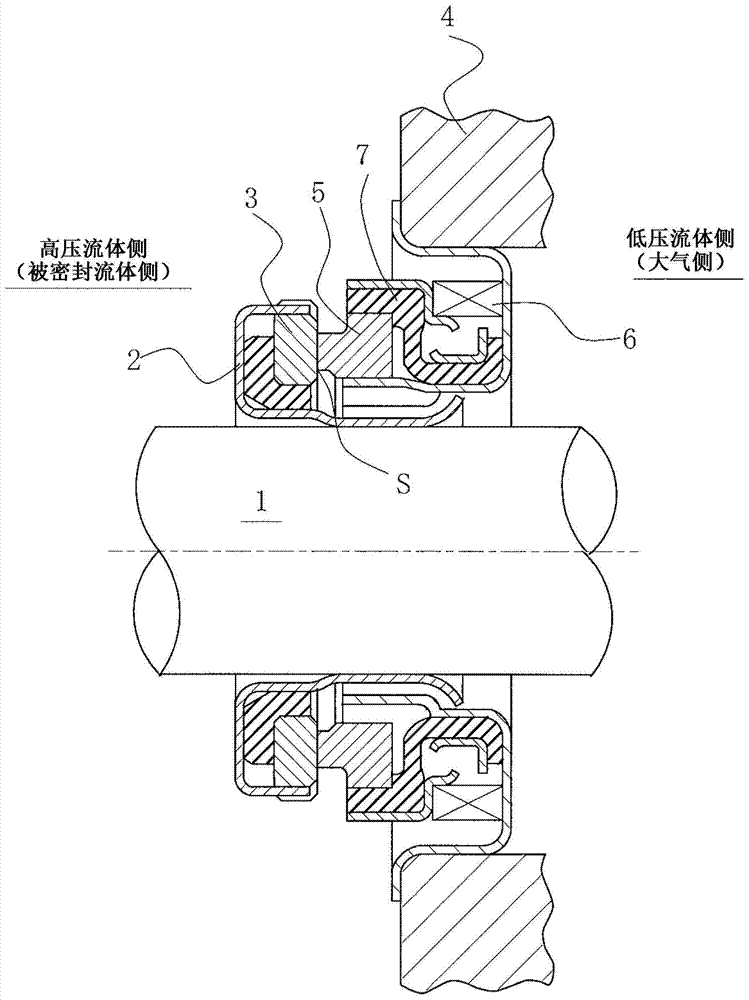
[0067] figure 1 It is a longitudinal sectional view showing an example of a mechanical seal, and is a built-in type mechanical seal that seals the sealed fluid on the high-pressure fluid side that leaks from the outer circumference of the sliding surface toward the inner circumference, and is annular. The rotary ring 3 and the annular fixed ring 5 are pressed between the sliding surfaces S which are mirror-finished by grinding etc. The rotating ring 3 is provided on the side of the rotating shaft 1 that drives the pump impeller (not shown) on the high-pressure fluid side in a state capable of rotating integrally with the rotating shaft 1 via the sleeve 2. The fixed ring 5 is provided on the casing 4 of th...

Embodiment 2

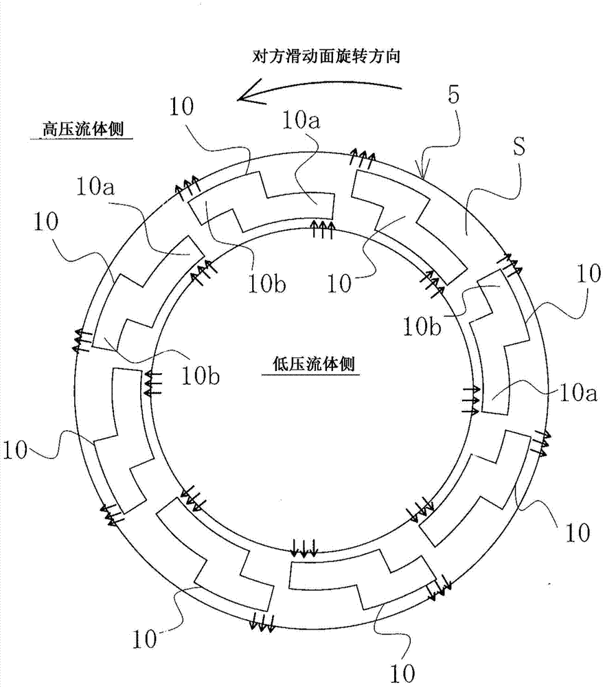
[0083] Figure 4 The sliding surface of the sliding member according to Example 2 of the present invention is shown, in order to figure 1 The case where a dent is formed on the sliding surface of the fixing ring 5 will be described as an example. In Example 2, the arrangement relationship of the dimples 10 in the circumferential direction is different from that of Example 1, but the other points are the same as in Example 1, and the same reference numerals are assigned to the same components, and overlapping descriptions are omitted.

[0084] exist Figure 4 Among the dimples 10 adjacent in the circumferential direction are arranged such that the positive pressure generating region 10b of the dimple 10 on the upstream side overlaps with the cavitation forming region 10a of the dimple 10 on the downstream side in the radial direction.

[0085] When dynamic pressure (positive pressure) is generated in the positive pressure generating region 10b of the dimple 10 on the upstrea...

Embodiment 3

[0088] Figure 5 The sliding surface of the sliding part of the embodiment 3 of the present invention is shown, in order to figure 1 The case where a dent is formed on the sliding surface of the fixing ring 5 will be described as an example. Example 3 differs from Example 2 in that the positive pressure generating region communicates with the high-pressure fluid side, but is the same as Example 2 in other respects, and the same reference numerals are assigned to the same components, and overlapping descriptions are omitted.

[0089] exist Figure 5 Among them, the positive pressure generating region 10b of each dent 10 communicates with the high-pressure fluid side through a communication groove 13 having a depth equal to or deeper than that of the dent 10 . exist Figure 5 Among them, the communication groove 13 is arranged radially outside the portion where the cavitation forming region 10a communicates with the positive pressure generating region 10b in the radial direc...


PUM


Abstract

Provided is a sliding part providing functionality for both leak prevention and lubrication with no relation to the magnitude of the pressure difference between the inner and outer circumference of a sliding face by drawing in a fluid with a cavitation region on the upstream side of a depressed portion, such as a dimple formed on the sliding face, and generating positive pressure between the sliding faces on the downstream side of the dimple. A sliding part is characterized in that: dimples are provided on the sliding face on one of a pair of sliding parts that slide relative to each other; a cavitation forming region on the upstream side of each dimple is disposed near a low pressure fluid side and a positive pressure generating region on the downstream side is disposed near a high pressure fluid side; and the fluid drawn in with the cavitation forming region of the dimple is returned to the high pressure fluid side from the positive pressure generating region by passing through the inside of the dimple.

Description

technical field [0001] The present invention relates to sliding parts suitable for use in, for example, mechanical seals, bearings, and other sliding parts. In particular, it relates to sliding parts such as seal rings and bearings that require fluid to intervene on sliding surfaces to reduce friction and prevent fluid leakage from the sliding surfaces. Background technique [0002] In a mechanical seal as an example of a sliding member, in order to maintain the sealing performance for a long period of time, it is necessary to balance the contradictory conditions of "sealing" and "lubrication". In particular, in recent years, in order to cope with environmental issues and the like, there has been an increased demand for low friction in order to reduce mechanical loss while preventing leakage of sealed fluid. As a method of reducing friction, it is possible to achieve a so-called fluid lubrication state in which dynamic pressure is generated between sliding surfaces by rotat...

Claims


Application Information

Patent Timeline
Patent Type & Authority Applications(China)
IPC IPC(8): F16J15/34
CPCF16J15/348F16J15/3412F16J15/34F16J15/40
Inventor 德永雄一郎
Owner EAGLE INDS
Why Eureka
Try Eureka