
Low temperature co-fired ceramic-based micro-electromechanical system (MEMS) packaging method

A technology of low-temperature co-fired ceramics and packaging methods, which is applied in the fields of crafts for producing decorative surface effects, decorative arts, microstructure devices, etc., to achieve the effects of reducing risks and losses, avoiding device failure, and good airtightness

Inactive Publication Date: 2010-11-03
PEKING UNIV
View PDF4 Cites 15 Cited by
  • Summary
  • Abstract
  • Description
  • Claims
  • Application Information

AI Technical Summary

Problems solved by technology

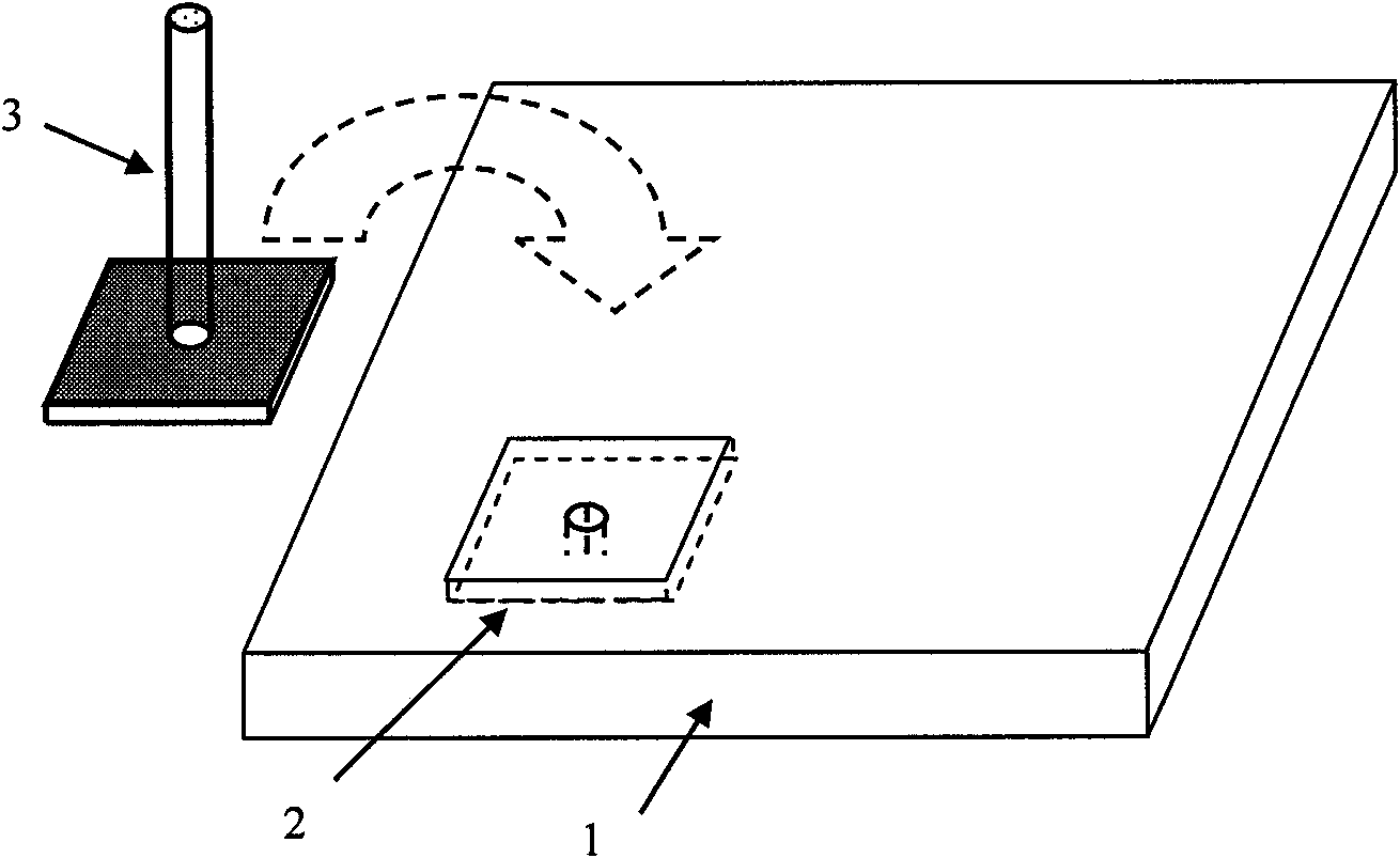
[0019] The purpose of the present invention is to address the defects of existing MEMS packaging methods, and propose a method for packaging MEMS using LTCC substrates, so as to improve the integration, stability and flexibility of MEMS packaging

Method used


Image

  • Low temperature co-fired ceramic-based micro-electromechanical system (MEMS) packaging method
  • Low temperature co-fired ceramic-based micro-electromechanical system (MEMS) packaging method
  • Low temperature co-fired ceramic-based micro-electromechanical system (MEMS) packaging method

Examples


Embodiment 1

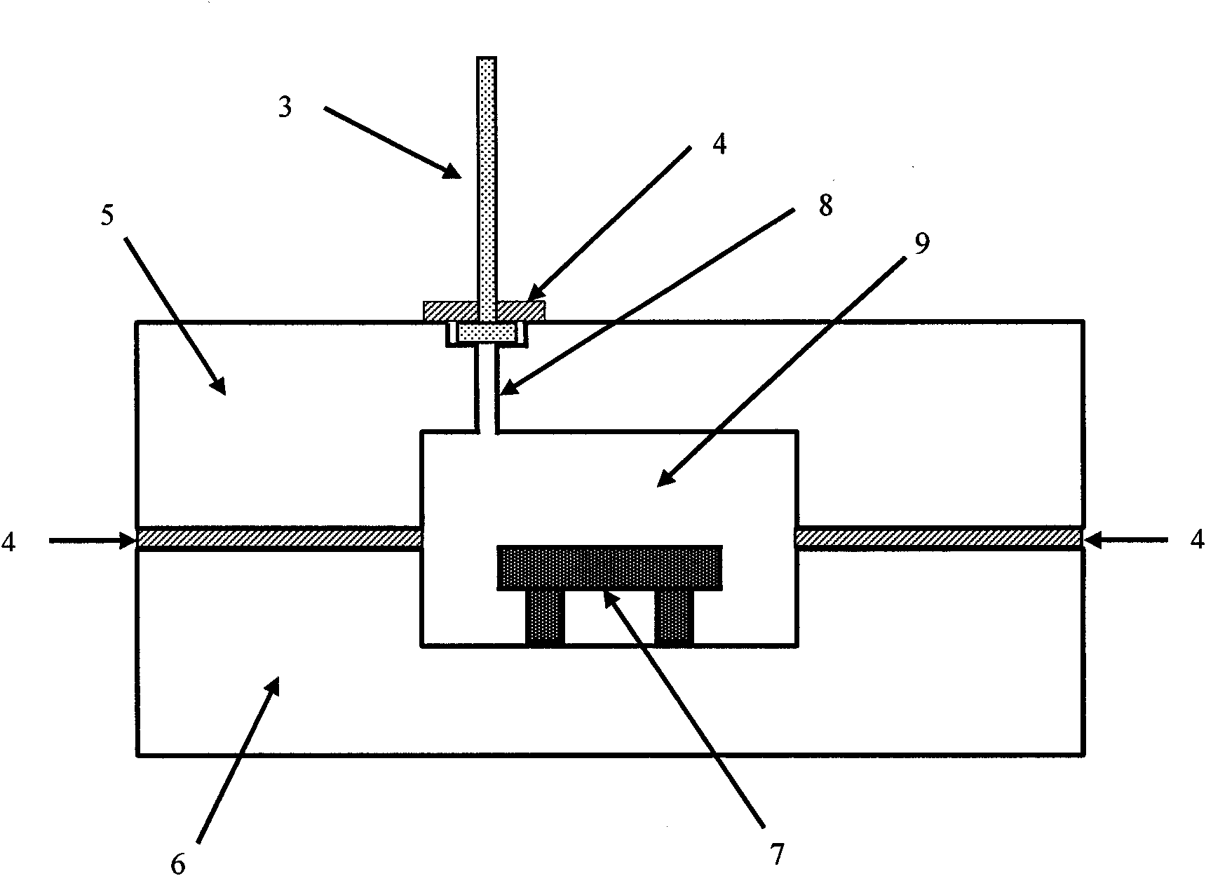
[0048] Vacuum packaging of MEMS using LTCC substrate embedded microfluidics (see figure 2 ), the steps are:

[0049] 1. The package is welded by two substrates. Process the upper substrate 5 first:

[0050] 1) According to the design, cut strip-shaped empty slots and square vertical holes on the LTCC green ceramic sheet by micro-machining methods such as micro-machining or corrosion, and then print metal paste to make metal interconnection wires and vertical interconnection via hole fillers and I / O pads;

[0051] 2) Accurately align and laminate the above-mentioned processed multi-layer green ceramic sheets, and sinter them into an integrated upper substrate 5 by using the conventional process of LTCC, and form vertical three-dimensional interconnection electrical signal lines on the substrate 5 at the same time of sintering , an embedded micro-channel 8 and an open cavity, wherein one end of the micro-channel 8 communicates with the top of the cavity, and the other end le...

Embodiment 2

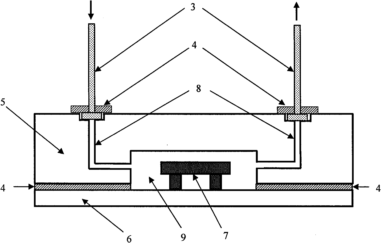
[0059] Using LTCC substrates to embed microfluidic channels for medical, biological, and chemical microfluidic transport cycles (see image 3 ), the steps are:

[0060] 1. The package is welded by two substrates, and the upper substrate 5 is processed first:

[0061] 1) Cut strip-shaped and square slots on the LTCC green ceramic sheet according to the design, and then print the metal paste on the LTCC green ceramic sheet to make metal interconnection wires, vertical interconnect via hole fillers and I / O pads;

[0062] 2) The above-mentioned processed multi-layer green ceramic sheets are precisely aligned and laminated, and sintered into an integrated substrate by using the conventional process of LTCC. The channel 8 and the open cavity 9 and the interface groove are respectively processed with an inlet micro-channel and an outlet micro-channel, and the micro-channel communicates with the side wall of the cavity;

[0063] 2. Put the metal tube 3 with the flange into the inter...


PUM


Abstract

The invention discloses a low temperature co-fired ceramic-based micro-electromechanical system (MEMS) packaging method. The method comprises the following steps of: preparing an upper low temperature co-fired ceramic substrate and a lower low temperature co-fired ceramic substrate respectively and forming a three-dimensional electrically-interconnected network, an embedded micro-channel and an open cavity in the upper substrate and / or the lower substrate; aligning the upper substrate with the lower substrate for packaging, packaging components and parts in the cavity and communicating the micro-channel with the cavity and the outside of a packaged body; and connecting an external micro-tube to the outlet of the micro-channel, which leads to the outside of the package body, and realizing gas or liquid flow between the cavity and the outside through the external micro-tube. The method has the advantages of improving the integration level, the stability and the flexibility of MEMS packaging, realizing vacuum packaging and heat dissipation of the components and parts in the cavity by conveying a circulating radiating medium through the micro-channel and conveying detection samples and the like to medical, biological or chemical MEMS components and parts in the packaging cavity through the micro-channel.

Description

technical field [0001] The invention belongs to the technical field of MEMS (micro-electromechanical system) packaging, in particular to a packaging method for integrating various MEMS devices and circuit chips. Background technique [0002] MEMS technology is based on the design and manufacturing technology in the micron / nano scale, and researches and develops micro-modules or systems that integrate micro-sensors, micro-actuators, and signal processing / control circuits to interfaces, communications, and power supplies. MEMS can complete tasks that are difficult for traditional electromechanical systems in the micro / nanoscale range, and can also be embedded in larger systems, raising their automation, intelligence and reliability to a new level. MEMS packaging is the last step in realizing MEMS integration, providing a working environment for the entire MEMS, and serving as an interconnection and supporting platform. [0003] In order to block external pollution and reduce ...

Claims


Application Information

Patent Timeline
Patent Type & Authority Applications(China)
IPC IPC(8): B81C1/00
Inventor 缪旻淦华金玉丰
Owner PEKING UNIV
Learn More