
a comparator

A comparator and input tube technology, applied in the field of comparators, can solve the problems of low hysteresis accuracy of comparators, achieve the effect of realizing hysteresis voltage and hysteresis direction, and realizing adjustable and high hysteresis accuracy

Active Publication Date: 2021-07-30
MICROTERA SEMICON (GUANGZHOU) CO LTD
View PDF5 Cites 0 Cited by
  • Summary
  • Abstract
  • Description
  • Claims
  • Application Information

AI Technical Summary

Problems solved by technology

[0005] In view of the shortcomings of the prior art described above, the purpose of the present invention is to provide a

Method used


Image

  • a comparator
  • a comparator
  • a comparator

Examples


Embodiment 1

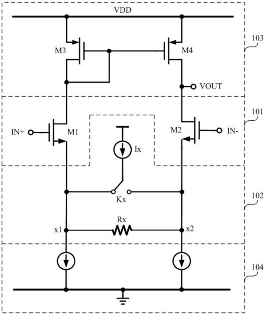
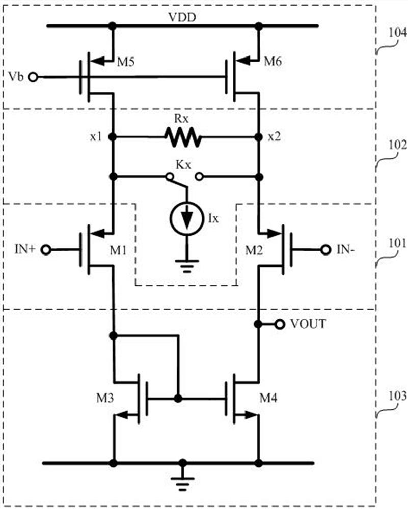
[0047] Such as figure 1 and 2 As shown, this embodiment provides a comparator, and the comparator includes:

[0048] The input pair tube 101 includes a positive terminal input tube M1 and a negative terminal input tube M2 for inputting the positive terminal signal IN+ and the negative terminal signal IN- to be compared;

[0049] The hysteresis control module 102 is connected to the source of the positive input transistor M1 and the source of the negative input transistor M2, and is used to control the positive input transistor when the input pair transistor 101 is an NMOS transistor. The source of M1 or the source of the negative input transistor M2 injects a set current Ix to control the hysteresis voltage; The source of the negative input transistor M2 draws a set current Ix to control the hysteresis voltage.

[0050] As an example, such as figure 1 and 2 As shown, the comparator also includes: a load module 103 and a current bias module 104; when the input pair tube 10...

Embodiment 2

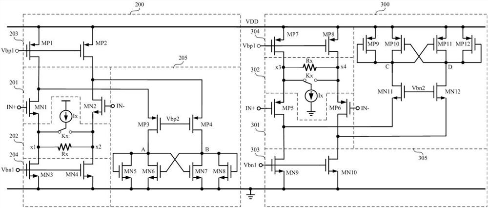
[0058] Such as image 3 As shown, this embodiment provides a comparator, the comparator includes: a first comparison unit 200 and a second comparison unit 300, and the first comparison unit 200 includes: an NMOS input pair transistor 201 and a first hysteresis control module 202. The second comparison unit 300 includes: a PMOS input pair transistor 301 and a second hysteresis control module 302, wherein,

[0059] The NMOS input pair tube 201 includes a positive NMOS input tube MN1 and a negative NMOS input tube MN2, which are used to input the positive terminal signal IN+ and the negative terminal signal IN- to be compared;

[0060] The first hysteresis control module 202 is connected to the source of the positive NMOS input transistor MN1 and the source of the negative NMOS input transistor MN2, for controlling the source of the positive NMOS input transistor MN1 or the source of the negative NMOS input transistor MN2. The source of the negative-end NMOS input transistor MN2...


PUM


Abstract

The present invention provides a comparator, the comparator includes: an input pair tube, including a positive terminal input tube and a negative terminal input tube, for inputting a positive terminal signal and a negative terminal signal to be compared; a hysteresis control module connected to the The source of the positive input transistor and the source of the negative input transistor are used to pass through the source of the positive input transistor or the negative input transistor when the input pair is an NMOS transistor. The source injects a set current to control the hysteresis voltage; when the input pair tube is a PMOS tube, the hysteresis is controlled by drawing a set current from the source of the positive input tube or the source of the negative input tube Voltage. The comparator provided by the invention solves the problem of low hysteresis accuracy of the existing comparator.

Description

technical field [0001] The invention belongs to the field of integrated circuit design, in particular to a comparator. Background technique [0002] The comparator can be used as a sub-module of most analog-to-digital converters, or it can be used alone as a functional module in the field of analog control, so it can be integrated in the MCU as an important functional module. [0003] Comparator hysteresis refers to the difference between the input threshold corresponding to the comparator output jumping from high to low and from low to high. The control field of all requires precise control of hysteresis, and it is not 0. Because the hysteresis is 0, at this time, if the input changes slowly and there is random noise jitter, the output will switch back and forth between high and low repeatedly. This situation will cause the control terminal to fail to grasp the specific state, and seriously cause system chaos. It can be seen that accurate hysteresis can control the compar...

Claims


Application Information

Patent Timeline
Patent Type & Authority Patents(China)
IPC IPC(8): H03M1/12
CPCH03M1/12
Inventor 刘森张均安李建平向可强符韬班桂春
Owner MICROTERA SEMICON (GUANGZHOU) CO LTD
Learn More