
A laparoscopic uterus lifting fixer for fixing the cervix of the cervix

A laparoscope and fixator technology, applied in the field of gynecological surgery, can solve the problems of affecting efficiency, inconvenient operation, cumbersome inconvenience and the like, and achieve the effect of improving intraoperative efficiency

Active Publication Date: 2021-11-23
SHANDONG FIRST MEDICAL UNIV & SHANDONG ACADEMY OF MEDICAL SCI
View PDF7 Cites 0 Cited by
  • Summary
  • Abstract
  • Description
  • Claims
  • Application Information

AI Technical Summary

Problems solved by technology

At present, there are mainly two methods used clinically. One method is to use non-invasive grasping forceps or other instruments under the laparoscope to pull the uterus upward or sideways to expose the surgical area, but the method requires additional puncture. The operating instrument is placed in the hole, and the instrument for pulling the uterus may interfere with the operation of other laparoscopic instruments, so it is inconvenient to operate; another method is to insert the uterine lifter through the vagina by the assistant to push the uterus in the desired direction, but the The operation needs to be completed by the second assistant, so that the laparoscopic surgery that can be completed by 2 doctors needs 3 doctors to complete, which virtually increases the medical cost; Among them, after the fixer is arranged, it will make it difficult to carry out medical operations in front of the uterus, resulting in greater obstacles. In the process of arrangement, when the lifting fixer is used, both sides are fixed on the two sides of the gynecological operating bed, so special straps are required. With the support of the operating bed (most of the conventional gynecological operating beds do not have it), the angle and position of the lifting part need to be adjusted and locked again when lifting the uterus, which is cumbersome and inconvenient, and seriously affects the efficiency during operation

Method used


Image

  • A laparoscopic uterus lifting fixer for fixing the cervix of the cervix
  • A laparoscopic uterus lifting fixer for fixing the cervix of the cervix
  • A laparoscopic uterus lifting fixer for fixing the cervix of the cervix

Examples


Embodiment Construction

[0034] The following description serves to disclose the present invention to enable those skilled in the art to carry out the present invention. The preferred embodiments described below are only examples, and those skilled in the art can devise other obvious variations.

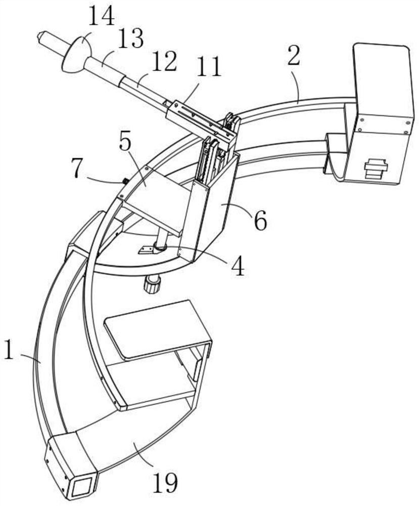
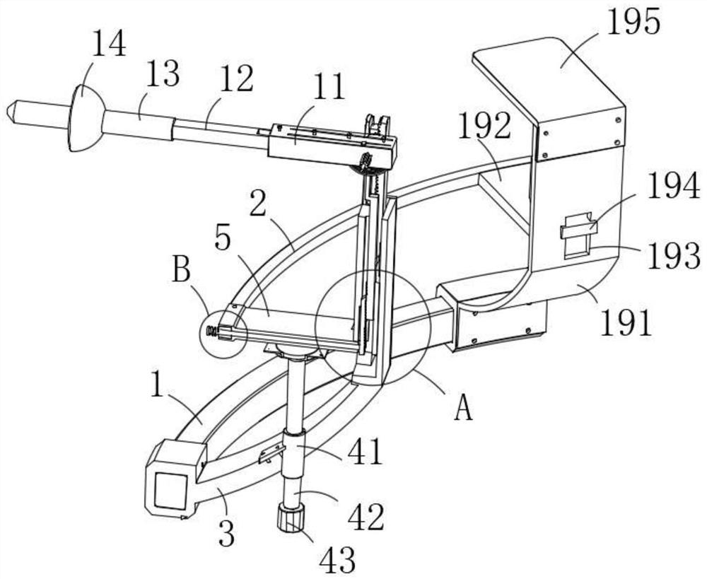
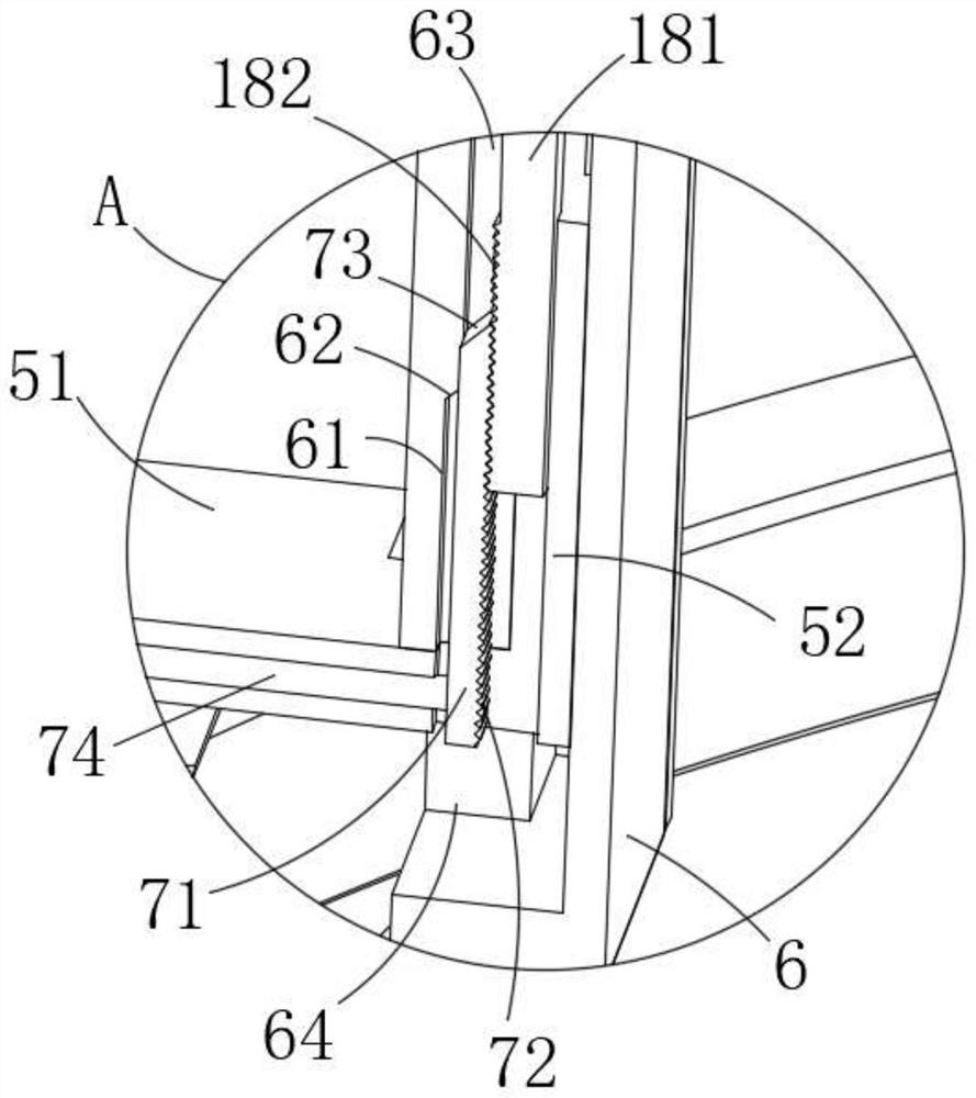
[0035] Such as Figure 1-Figure 14 A laparoscopic uterine lifting fixer for conveniently fixing the cervix is ​​shown, including a lower arc rod 1, a coaxial upper arc rod 2 is arranged above the lower arc rod 1, and the middle of the lower arc rod 1 is fixed It is connected with a connecting arc plate 3 close to its axis, the upper end of the connecting arc plate 3 is fixedly connected with a connecting box 6, and the rear end surface of the connecting box 6 is slidably connected with a movable plate 5 along the vertical direction, and the movable plate 5 The rear end is fixedly connected to the upper arc rod 2, and the outer surface of the connecting arc plate 3 is provided with a lifting mechanism 4 that...


PUM


Abstract

The present invention relates to the technical field of gynecological surgery, and in particular to a laparoscopic uterus lifting fixer for fixing the cervix, which includes a lower arc rod, and a coaxial upper arc rod is arranged above the lower arc rod. The middle of the lower arc rod is fixedly connected with a connecting arc plate approaching its axis, the upper end of the connecting arc plate is fixedly connected with a connecting box, and the rear end surface of the connecting box slides vertically and is connected with a movable plate, and the rear end of the movable plate is fixedly connected to the upper arc rod, and the outer surface of the connected arc plate is provided with a lifting mechanism that controls the sliding of the upper end of the movable plate. It can make the entire fixer install smoothly and lift the cervix, improve the efficiency of the operation, and fit the actual use. After the arrangement, it will not block the front of the uterus and the position of the treatment hole, so as to ensure the normal operation of medical care.

Description

technical field [0001] The invention relates to the technical field of gynecological surgery, in particular to a laparoscopic uterus lifting fixer for fixing the cervix of the uterus. Background technique [0002] In many gynecological laparoscopic operations involving the pelvic cavity, due to the narrow space of the pelvic cavity, it is generally necessary to retract the uterus upwards or sideways to better expose the surgical operation area. At present, there are mainly two methods used clinically. One method is to use non-invasive grasping forceps or other instruments under the laparoscope to pull the uterus upward or sideways to expose the surgical area, but the method requires additional puncture. The operating instrument is placed in the hole, and the instrument for pulling the uterus may interfere with the operation of other laparoscopic instruments, so it is inconvenient to operate; another method is to insert the uterine lifter through the vagina by the assistant t...

Claims


Application Information

Patent Timeline
Patent Type & Authority Patents(China)
IPC IPC(8): A61B17/42
CPCA61B17/4241A61B2017/4216
Inventor 张毅芳范加诚张毅张倩倩刘西鹏徐如雪
Owner SHANDONG FIRST MEDICAL UNIV & SHANDONG ACADEMY OF MEDICAL SCI
Learn More