
Converter Transformer Partial Discharge Model Operating Mechanism

A converter transformer and partial discharge technology, which is applied in the field of converter transformer partial discharge model operating mechanism, can solve the problems of long time interval, inability to realize the pressurization mode of the needle plate discharge model, cumbersome operation steps, etc., so as to reduce the repetitive workload Effect

Active Publication Date: 2022-07-05
ELECTRIC POWER RES INST OF STATE GRID ZHEJIANG ELECTRIC POWER COMAPNY
View PDF9 Cites 0 Cited by
  • Summary
  • Abstract
  • Description
  • Claims
  • Application Information

AI Technical Summary

Problems solved by technology

[0007] 3) When the needle plate discharge model needs to adjust the discharge capacity, the model must be taken out, adjusted and then put into the transformer; such operation steps are extremely cumbersome, the installation workload is huge, and the time interval of a single test is long
[0008] 4) The pin-plate discharge model cannot realize two different ways of applying voltage, 20kV voltage is applied from the metal tip electrode, and 60kV voltage is applied from the plate electrode

Method used


Image

  • Converter Transformer Partial Discharge Model Operating Mechanism
  • Converter Transformer Partial Discharge Model Operating Mechanism
  • Converter Transformer Partial Discharge Model Operating Mechanism

Examples


Embodiment Construction

[0040] The technology of the present invention will be described in detail below with reference to the specific embodiments. It should be understood that the following specific embodiments are only used to help those skilled in the art to understand the present invention, but not to limit the present invention.

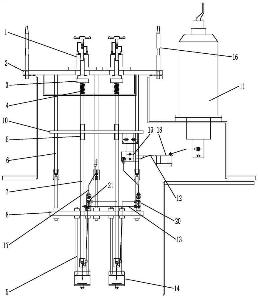
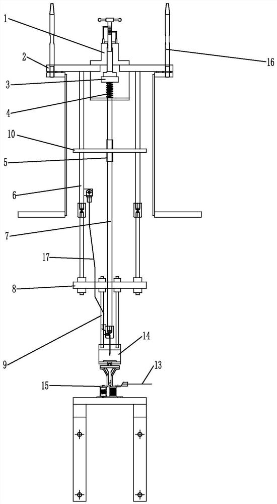
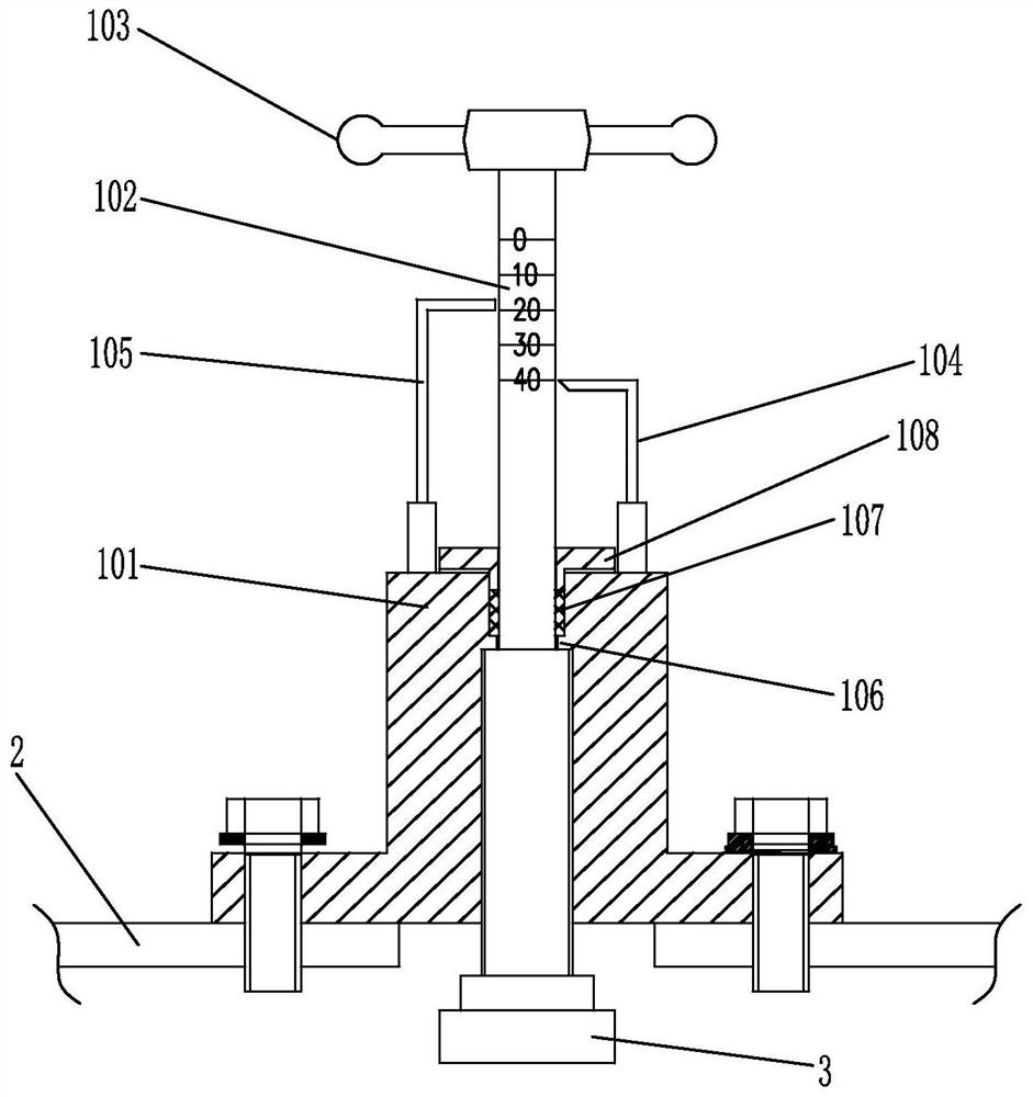
[0041] like Figure 1-3 The shown operating mechanism of the partial discharge model of the converter transformer is composed of a fixed frame and an electrode spacing adjusting device 1 installed on the fixed frame.

[0042] The fixed frame is composed of a fixed installation rod 6 with an adjustable length, an insulating member 8, an insulating fixed rod 9 and a mounting flange 2. One end of the fixed installation rod 6 is fixedly connected to the insulating member 8, and the other end is connected to the installation method. The flange 2 is fixedly connected, and the mounting flange 2 is fixed on the top cover of the transformer oil tank.

[0043] The electrode spa...


PUM


Abstract

The invention discloses a partial discharge model operating mechanism of a converter transformer. The invention includes a fixed frame and an electrode spacing adjustment device installed on the fixed frame; the fixed frame includes a fixed installation rod with adjustable length, an insulating member, an insulating fixed rod and a mounting flange, and one end of the fixed installation rod is connected to The insulating part is fixedly connected, and the other end is fixedly connected with the installation flange, and the installation flange is fixed on the top cover of the transformer tank; the electrode spacing adjustment device is installed on the installation flange, and the electrode spacing adjustment device The bottom end is connected to a pressing block, the bottom of the pressing block is fixedly connected to the upper end of the connecting rod, the connecting rod penetrates the insulating member, and the lower end of the connecting rod is connected to the metal tip electrode in the needle plate discharge model; the insulating member and the The base of the needle plate discharge model is connected by an insulating fixing rod. The invention enables accurate positioning of the needle plate discharge model during installation, facilitates the adjustment of the discharge amount outside the transformer, and can realize two different pressurization modes.

Description

technical field [0001] The invention belongs to the field of partial discharge defect simulation of insulating parts of converter transformers, in particular to a partial discharge model operating mechanism of a converter transformer. Background technique [0002] As the most critical equipment in the DC transmission project, the UHV converter transformer directly affects the safe operation of the entire UHV DC transmission project. The fault state research of the transformer body, including partial discharge defect simulation and signal acquisition of insulating parts, vibration state perception of internal structural parts, transformer oil temperature distribution measurement, winding overheat defect simulation, etc. Accuracy and reliability provide a scientific basis for equipment status evaluation and operation and maintenance decision-making. [0003] For the partial discharge defect simulation of insulating parts, the method of arranging the needle plate discharge mod...

Claims


Application Information

Patent Timeline
Patent Type & Authority Patents(China)
IPC IPC(8): G01R31/12G01R1/04
CPCG01R31/1227G01R1/0408Y02P10/25
Inventor 蔺家骏郑一鸣邵先军朱佳金玉琪詹江杨李晨孙翔杨智王强李祥姜炯挺贡春艳
Owner ELECTRIC POWER RES INST OF STATE GRID ZHEJIANG ELECTRIC POWER COMAPNY
Learn More