De-emphasis type continuous-time linear equalizer architecture
A linear equalizer and de-emphasis technology, applied in balanced-unbalanced networks, baseband systems, shaping networks in transmitter/receiver, etc. The same problem, to achieve the effect of increasing the Nyquist frequency, improving the peaking ability, and extending the bandwidth
- Summary
- Abstract
- Description
- Claims
- Application Information
AI Technical Summary
Benefits of technology
Problems solved by technology
Method used
Image

Examples
Embodiment 1
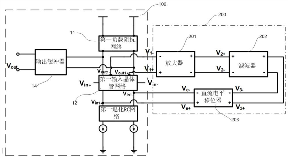
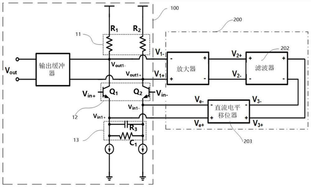
[0058] refer to Figure 2 to Figure 4 It is a schematic structural diagram of a de-emphasis continuous-time linear equalizer architecture related to Embodiment 1.
[0059] refer to figure 2 , the equalizer main circuit 100 further includes a first input transistor network 12 , a first load impedance network 11 and a first degenerate RC network 13 . Among them, the main input interface V in+ , main input interface V in- , the secondary output interface, the first degenerate RC network 13 and the first load impedance network 11 are respectively connected to the first input transistor network 12, and the first load impedance network 11 and the first input transistor network 12 are connected to the main output interface V out . The first degenerate RC network 13 is also connected to the secondary input interface with the first input transistor network 12 . The end of the first load impedance network 11 away from the first input transistor 12 is connected to a DC voltage sour...
Embodiment 2
[0079] refer to Figure 5 with Figure 7 It is a specific structural diagram of the de-emphasis continuous-time linear equalizer architecture related to the second embodiment.
[0080] refer to Figure 5 , the equalizer main circuit 100 is multi-stage, at least including a first-level main circuit 101 and a second-level main circuit 102 connected with the first-level main circuit 101, and the first-level main circuit 101 includes a first input transistor network 12, a first load impedance network 11 and the first degenerate RC network 13 , the secondary main circuit 102 includes a second input transistor network 22 , a second load impedance network 21 and a second degenerate RC network 23 . Among them, the main input interface V in+ , main input interface V in- respectively connected to the first input transistor network 12, the main output interface V out Connected to the second input transistor network 22 and the second load impedance network 21 , the secondary input in...
Embodiment 3
[0089] refer to Image 6 with Figure 8 It is a specific structural diagram of the de-emphasis continuous-time linear equalizer architecture related to the third embodiment.
[0090] refer to Image 6 , the equalizer main circuit 100 is multi-stage, at least including a first-level main circuit 101 and a second-level main circuit 102 connected with the first-level main circuit 101, and the first-level main circuit 101 includes a first input transistor network 12, a first load impedance network 11 and the first degenerate RC network 13 , the secondary main circuit 102 includes a second input transistor network 22 , a second load impedance network 21 and a second degenerate RC network 23 . Among them, the main input interface V in+ and main input interface V in- Connected to the second input transistor network 22, the main output interface V out Connected to the first input transistor network 12 and the first load impedance network 11 , the secondary input interface and the...
PUM
 Abstract
Description
Claims
Application Information
 - R&D
- Intellectual Property
- Life Sciences
- Materials
- Tech Scout
- Unparalleled Data Quality
- Higher Quality Content
- 60% Fewer Hallucinations
Browse by: Latest US Patents, China's latest patents, Technical Efficacy Thesaurus, Application Domain, Technology Topic, Popular Technical Reports.
© 2025 PatSnap. All rights reserved.Legal|Privacy policy|Modern Slavery Act Transparency Statement|Sitemap|About US| Contact US: help@patsnap.com