Supercharge Your Innovation With Domain-Expert AI Agents!

Continuous time linear equalizer and signal transceiving circuit

A linear equalizer and circuit technology, applied in the direction of reducing distortion, improving control circuits, electrical components, automatic tone/bandwidth control, etc., can solve problems such as large signal transmission loss, signal loss, and signal compensation

Pending Publication Date: 2021-04-30
SOUTH UNIVERSITY OF SCIENCE AND TECHNOLOGY OF CHINA
View PDF5 Cites 0 Cited by
  • Summary
  • Abstract
  • Description
  • Claims
  • Application Information

AI Technical Summary

Problems solved by technology

Due to non-ideal factors such as parasitic capacitance and skin effect in the transmission channel and transimpedance amplifier, the signal will suffer a large transmission loss in the middle and low frequency bands and high frequency bands
[0003] In the prior art, CTLE usually uses a MOS transistor as a differential amplifier, and the drain is connected to a series resistor and inductor as an output terminal, and the parallel resistor and capacitor are coupled to the source stage of the MOS transistor, using inductance peaking technology and capacitance degradation technology The two zero points introduced in the high frequency band, and due to non-ideal factors such as skin effect and dielectric loss, the signal will also experience serious signal loss in the middle and low frequency bands, which makes the signal distorted, and the CTLE of the prior art cannot correct Compensation for mid- and low-frequency signals, resulting in signal distortion

Method used


Image

  • Continuous time linear equalizer and signal transceiving circuit
  • Continuous time linear equalizer and signal transceiving circuit
  • Continuous time linear equalizer and signal transceiving circuit

Examples


Embodiment Construction

[0034] The present invention will be further described in detail below in conjunction with the accompanying drawings and embodiments. It should be understood that the specific embodiments described here are only used to explain the present invention, but not to limit the present invention. In addition, it should be noted that, for the convenience of description, only some structures related to the present invention are shown in the drawings but not all structures.

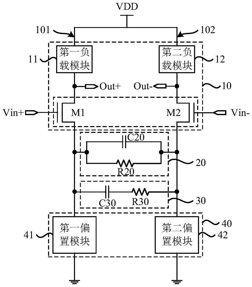
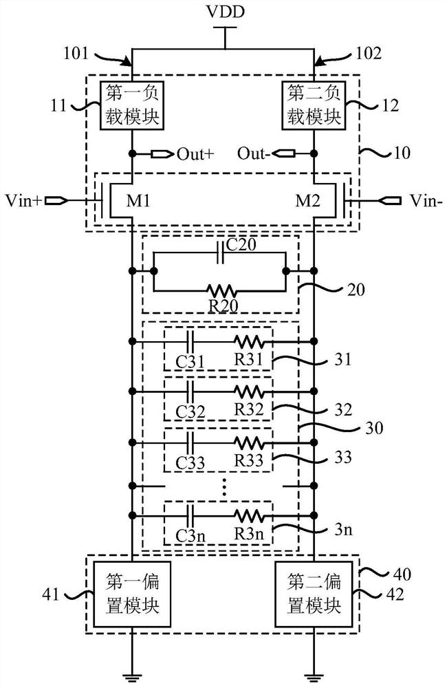
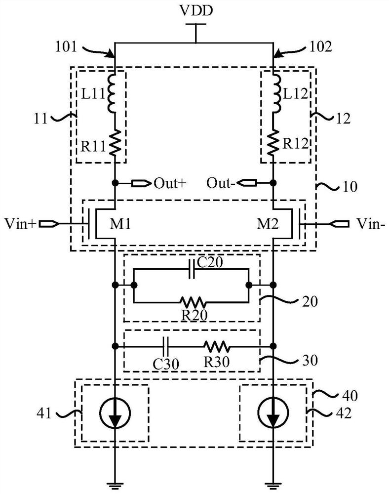
[0035] An embodiment of the present invention provides a continuous time linear equalizer, which can be applied in a communication system to compensate transmission loss in a transmission link of the communication system. figure 1 It is a schematic structural diagram of a continuous-time linear equalizer provided by an embodiment of the present invention. Such as figure 1 As shown, the continuous-time linear equalizer includes input terminals (Vin+, Vin-), output terminals (Out+ and Out-), a differential amplifie...


PUM


Abstract

The embodiment of the invention discloses a continuous time linear equalizer and a signal transceiving circuit. The continuous time linear equalizer comprises an input end, an output end and a differential amplification circuit electrically connected with the input end and the output end respectively, and the differential amplification circuit comprises a first branch circuit and a second branch circuit which are connected in parallel; the first frequency compensation circuit and the at least one second frequency compensation circuit are electrically connected between the first branch circuit and the second branch circuit, and the first frequency compensation circuit, the second frequency compensation circuit and the second frequency compensation circuits are connected in parallel; the first frequency compensation circuit is at least used for compensating high-frequency loss; the second frequency compensation circuit is at least used for compensating medium-low frequency loss; wherein the first frequency compensation circuit is an RC parallel circuit, and the second frequency compensation circuit is an RC series circuit. According to the embodiment of the invention, high-frequency signals and low-frequency signals can be compensated at the same time, and the accuracy of signal transmission is ensured.

Description

technical field [0001] Embodiments of the present invention relate to the technical field of signal transceiving, and in particular, to a continuous-time linear equalizer and a signal transceiving circuit. Background technique [0002] A Continuous Time Linear Equalizer (CTLE) is a core device at a signal receiving end or a signal output end of a communication system. Taking the signal receiving end in the optical communication system as an example, the transimpedance amplifier in the signal receiving end converts the tiny current signal output by the photodiode into a larger voltage signal as the input signal of CTLE. Due to non-ideal factors such as parasitic capacitance and skin effect in the transmission channel and transimpedance amplifier, the signal will suffer a large transmission loss in the middle and low frequency bands and high frequency bands. [0003] In the prior art, CTLE usually uses a MOS transistor as a differential amplifier, and the drain is connected t...

Claims


Application Information

Patent Timeline
Patent Type & Authority Applications(China)
IPC IPC(8): H03G5/16H03G1/04
CPCH03G5/165H03G1/04
Inventor 潘权罗雄师丘璋于洪宇汪青
Owner SOUTH UNIVERSITY OF SCIENCE AND TECHNOLOGY OF CHINA
Features
  • R&D
  • Intellectual Property
  • Life Sciences
  • Materials
  • Tech Scout
  • Unparalleled Data Quality
  • Higher Quality Content
  • 60% Fewer Hallucinations
Learn More