Intelligent detection device for customizing personalized cups and use method of intelligent detection device
An intelligent detection, right cup technology, applied in bras, applications, bras, etc., can solve the problems of poor measurement effect, inability to take into account the cup shape and pressure, etc., to improve comfort and good measurement effect.
- Summary
- Abstract
- Description
- Claims
- Application Information
AI Technical Summary
Problems solved by technology
Method used
Image
Examples
Embodiment 1
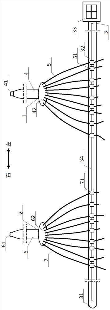
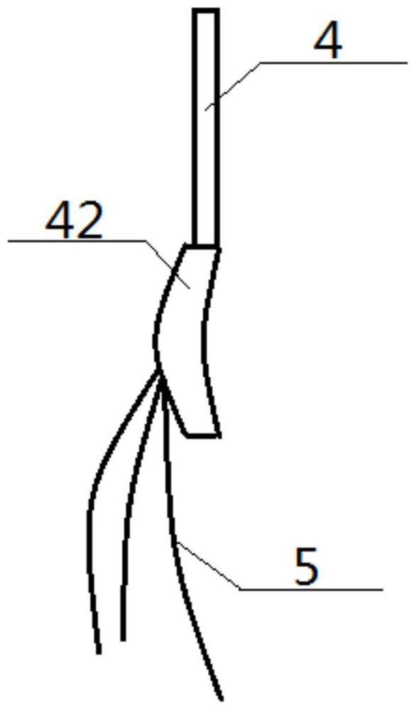
[0065] see figure 1 — Figure 8 , an intelligent detection device for customizing personalized breast cups, the intelligent detection device includes a body strap 3, a left cup detection unit 1 and a right cup detection unit 2, and the body strap 3 includes a belt free end 31 connected in sequence, The strap body 32 and the strap fixed end 33, the strap free end 31 and the strap fixed end 33 carry out snap fit, and the front of the middle part of the strap body 32 is provided with a long chute 34 coaxial with the strap body 32 The left cup detection unit 1 and the right cup detection unit 2 are both located above the belt body 32, and are arranged opposite to each other left and right; the left cup detection unit 1 includes a left vertical belt 4 and a plurality of left measuring belts 5, The top of the left vertical strap 4 is provided with a left fixing part 41, the bottom of the left vertical strap 4 is connected with the tops of all the left measuring straps 5, and the bo...
Embodiment 2
[0071] Basic content is the same as embodiment 1, the difference is:
[0072] The structures of the left measuring tape 5 and the right measuring tape 7 are consistent, and both include a measuring tape body 52 and a plurality of force-measuring chambers 53 arranged inside thereof, and all force-measuring chambers 53 are arranged in sequence inside the measuring tape body 52, A spacer 54 is sandwiched between adjacent force-measuring chambers 53 ; graphite, carbon black or metal powders are arranged inside the force-measuring chambers 53 . Preferably, graphite, carbon black or metal powder is arranged in the force-measuring cavity 53 by filling, injection or screen printing.
Embodiment 3
[0074] Basic content is the same as embodiment 1, the difference is:
[0075] The structures of the left sliding block 51 and the right sliding block 71 are consistent, and both include a clamping part 72 and a sliding part 73. The clamping part 72 includes an outer cylinder 721 and a belt threading cavity 722 opened inside it. The inside of the belt cavity 722 passes through the left measuring belt 5 or the right measuring belt 7. The sliding part 73 includes a connecting shaft 731 and a sliding plate 732. The top end of the connecting shaft 731 is vertically connected to the bottom of the outer cylinder 721. , the bottom end of the connecting shaft 731 is vertically connected to the middle part of the sliding plate 732, and the outer cylinder 721, the connecting shaft 731, and the sliding plate 732 are clamped to form an inner groove 733; Cavity 341 and chute inner cavity 342, the two sides of described chute outer cavity 341 are clamping arm 343, and described clamping arm ...
PUM
 Abstract
Description
Claims
Application Information
 - R&D
- Intellectual Property
- Life Sciences
- Materials
- Tech Scout
- Unparalleled Data Quality
- Higher Quality Content
- 60% Fewer Hallucinations
Browse by: Latest US Patents, China's latest patents, Technical Efficacy Thesaurus, Application Domain, Technology Topic, Popular Technical Reports.
© 2025 PatSnap. All rights reserved.Legal|Privacy policy|Modern Slavery Act Transparency Statement|Sitemap|About US| Contact US: help@patsnap.com


