Rapid breaking structure for over-grouting part of pile top of cast-in-place pile

A technology of cast-in-place piles and pile tops, which can be applied to foundation structure engineering, foundation structure testing, sheet pile walls, etc., can solve problems such as low efficiency, laborious operation, and huge labor costs.

Active Publication Date: 2021-07-16
NANJING AGRICULTURAL UNIVERSITY
View PDF9 Cites 0 Cited by
  • Summary
  • Abstract
  • Description
  • Claims
  • Application Information

AI Technical Summary

Problems solved by technology

First of all, the over-filled part of the pile top is hammered and broken by the workers with hammer heads. The efficiency is low, the speed is slow, the operation is laborious, and the labor cost is high. However, there are a large number of cast-in-place piles in the construction site, knocking off the super-filled part of the concrete on the top of all cast-in-place piles will generate huge labor costs, and the economy is too poor; It may damage the longitudinal main reinforcement of the super-filled part and the remaining concrete of the pile head below, which will affect the quality and performance of the pile body; and, also due to the randomness of manual knocking, the fracture of the pile body will be uneven, that is, the pile body will be damaged. The height of the damage is inconsistent, and the top elevation of the remaining pile heads is difficult to control, and naturally it is impossible to ensure that the height of the remaining pile heads extending into the cap meets the design requirements

Method used


Image

  • Rapid breaking structure for over-grouting part of pile top of cast-in-place pile
  • Rapid breaking structure for over-grouting part of pile top of cast-in-place pile
  • Rapid breaking structure for over-grouting part of pile top of cast-in-place pile

Examples


Embodiment Construction

[0021] The present invention will be further described below in conjunction with the accompanying drawings and specific embodiments.

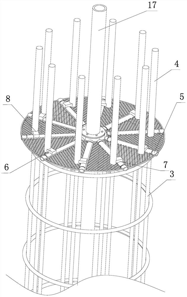
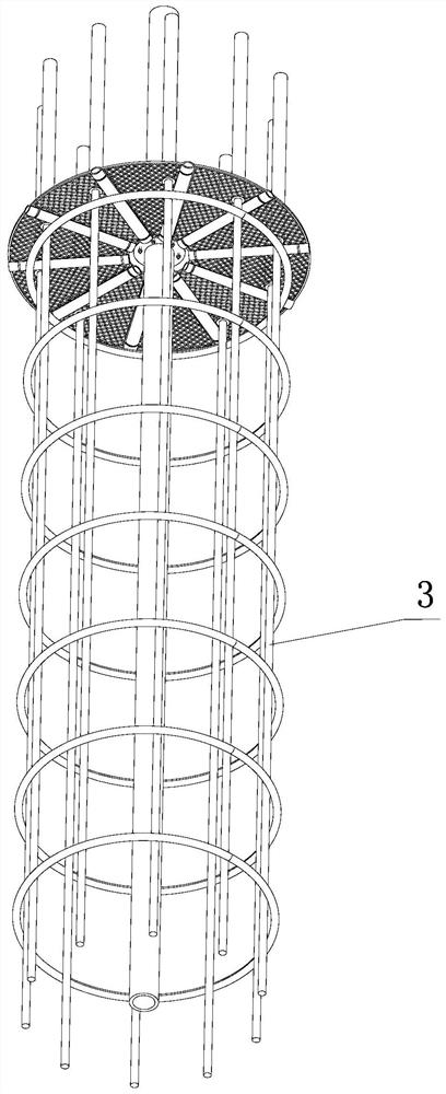
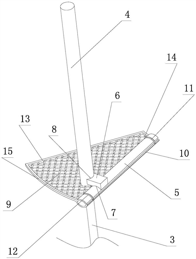
[0022] Such as Figure 1 to Figure 7 Shown, the quick breaking structure of cast-in-situ pile top superfilling part of the present invention, it comprises the pile top superfilling part 1 that will be broken and the remaining normal pile section 2 that is positioned at the pile top superfilling part 1 below after breaking, perfusion The reinforcement cage of the pile includes multiple stirrups and multiple longitudinal main reinforcements 3 in the normal pile section 2, and the reinforcement cage only includes multiple longitudinal main reinforcements 3 without stirrups in the super-filled part 1.

[0023] Each longitudinal main rib 3 of the super-filling part 1 is fitted with a longitudinal sleeve 4 with the opening facing downward; the longitudinal sleeve 4 is coated with insulating substances such as butter or asphalt, and its function is to...


PUM


Abstract

The invention discloses a rapid breaking structure for the over-grouting part of the pile top of a cast-in-place pile. The rapid breaking structure comprises the pile top over-grouting part and a normal pile section below the pile top over-grouting part, and each longitudinal main rib of the over-grouting part is sleeved with a longitudinal sleeve with a downward opening; one side of each longitudinal sleeve is correspondingly provided with one transverse sleeve and one hot melting block; the cross section of each transverse sleeve is in a flat eye shape, and teach transverse sleeve comprises an upper cambered surface, a lower cambered surface, a left sharp corner and a right sharp corner; The single side of each transverse sleeve is opened outwards, the outer opening of each transverse sleeve is located on the side surface of the cast-in-place pile, the transverse sleeves are filled with water, and plugs are arranged at outer openings; the bottom cambered surfaces of the hot melting blocks are fixed with the upper cambered surfaces of the transverse sleeves in a hot melting manner, the side cambered surfaces of the hot melting connecting blocks are fixed with the outer walls of the longitudinal sleeves in a hot melting manner; and the bottom ring surfaces of the longitudinal sleeves are flush with the height interfaces of the transverse sleeves. The rapid breaking structure is rapid, efficient and labor-saving to operate, fractures are smooth, and the elevation of the fracture surface can be effectively controlled.

Description

technical field [0001] The invention relates to the technical field of foundation pile construction, in particular to a quick breaking structure for the superfilled part of the cast-in-situ pile top. Background technique [0002] The cast-in-place pile is a common form of foundation pile, and its construction steps are roughly as follows: use a pile driver to form a hole and use mud to protect the wall until the hole bottom level is drilled, then lower the steel cage, and then insert the pipe and pour concrete. In order to ensure the quality of the pile foundation, overfilling is required when pouring concrete, that is, pouring a certain height higher than the design elevation of the pile top, such as 1 meter. However, after overfilling, before pouring and tamping the concrete cap and the bottom plate in the later stage, the concrete on the overfilling part of the pile top must be knocked off and the longitudinal main reinforcement of the reinforcement cage must be leaked, a...

Claims


Application Information

Patent Timeline
Patent Type & Authority Applications(China)
IPC IPC(8): E02D9/00E02D33/00
CPCE02D9/005E02D33/00
Inventor 高新南李静张云清
Owner NANJING AGRICULTURAL UNIVERSITY
Why Eureka
Try Eureka