USB socket and manufacturing method thereof

A manufacturing method and technology of connectors, which are applied to the assembly/disassembly of contacts, fixing/insulating contact members, electrical components, etc., can solve the problems of simultaneous fixing in the upper and lower directions, high cost of mold opening, and inability to realize one-time or Double injection molding and other issues to achieve good appearance and reduce manufacturing costs

Pending Publication Date: 2021-07-23
SHENZHEN EVERWIN PRECISION TECH
View PDF5 Cites 1 Cited by
  • Summary
  • Abstract
  • Description
  • Claims
  • Application Information

AI Technical Summary

Problems solved by technology

There is a three-layer structure in the vertical direction, that is, two rows of terminal groups and the middle plate. During the injection molding process, the injection mold cannot simultaneously fix the two rows of terminal groups and the middle plate in the upper and lower directions, and it is impossible to realize one or two injection molding Molding, which requires three or as many as four injection molding passes to complete the product
Usually, the first terminal group, the metal middle plate, and the second terminal group are respectively subjected to one injection molding, and then the formed first and second terminal groups are superimposed and fixed for a third injection molding to complete the injection molding process. At least three sets of different injection molding molds are required, and the cost of mold opening is relatively high

Method used


Image

  • USB socket and manufacturing method thereof
  • USB socket and manufacturing method thereof
  • USB socket and manufacturing method thereof

Examples


Embodiment Construction

[0030] In order to make the objectives, technical solutions and advantages of the present application clearer, the technical solutions of the present application will be clearly and completely described below with reference to the specific embodiments of the present application and the corresponding drawings. Obviously, the described embodiments are only a part of the embodiments of the present application, but not all of the embodiments.

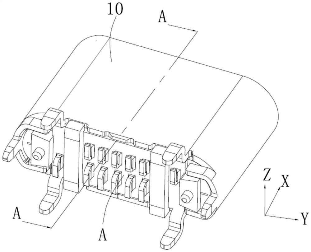
[0031] This application starts with figure 1 The indicated X direction is above the vertical direction (vertical direction), the Y direction is the left-right direction (horizontal direction), and the Z direction is the front-rear direction (vertical direction).

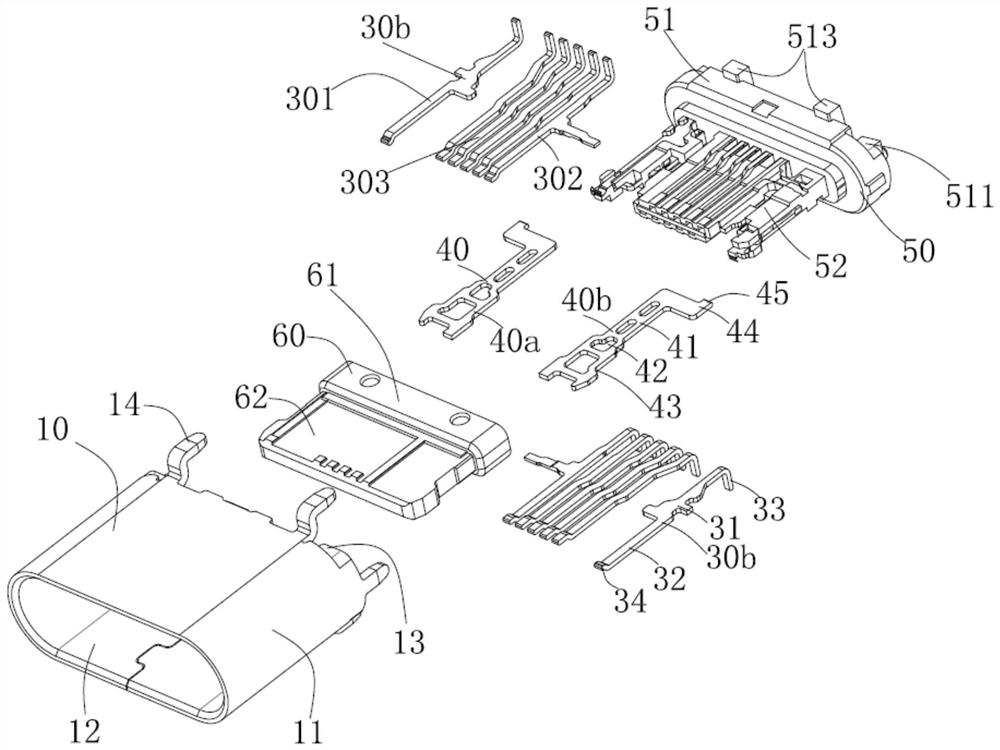
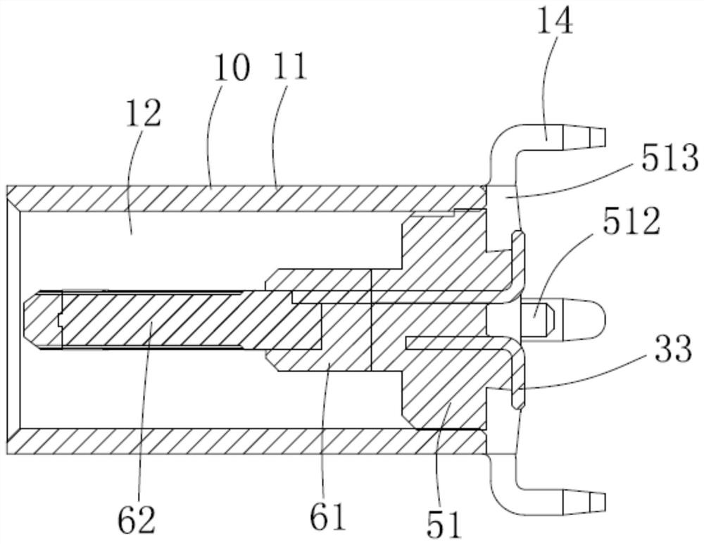
[0032] see Figure 1 to Figure 7 As shown, the USB socket of the present application includes a connector A and a metal shell 10 sleeved outside the connector A.

[0033]The metal shell 10 includes an annular shell 11 surrounding a cavity 12 penetrating up and down, hooks 13 ben...


PUM


Abstract

The invention provides a USB socket, which comprises a plug connector and a metal shell sleeved outside the plug connector, wherein the plug connector comprises a first terminal group, a second terminal group, a middle plate arranged between the first terminal group and the second terminal group, and an insulating body for fixedly holding the first terminal group, the second terminal group and the middle plate into a whole, the insulating body comprises an insulating base body which is formed by first injection molding and fixes the first terminal group, the second terminal group and the middle plate into a whole, and an insulating main body which is formed by second injection molding, the insulating base body comprises a base part located at the lower end and a front fixing part which extends upwards from the base part and fixes the first terminal group, the second terminal group and the upper end of the middle plate, and the insulating main body wraps the front fixing part and is provided with a transition part located on the upper side of the base part and a butt joint tongue part formed by extending upwards from the transition part. The invention further discloses a manufacturing method of the USB socket.

Description

technical field [0001] The present application relates to the field of electrical connectors, in particular to a USB socket and a manufacturing method thereof. Background technique [0002] Type C sockets generally include upper and lower rows of mutually independent terminal sets, a middle plate placed between the upper and lower rows of terminal sets, an insulating body that holds the two rows of terminal sets and the middle plate into one body, and sleeves on the insulating body outer shell. There is a three-layer structure in the vertical direction, that is, the upper and lower rows of terminal groups and the middle plate. During the injection molding process, the injection mold cannot fix the two rows of terminal groups and the middle plate at the same time in the upper and lower directions, and it is impossible to achieve one or two injections. molding, while three or as many as four injection moldings are required to complete the product. Usually, the first terminal...

Claims


Application Information

Patent Timeline
Patent Type & Authority Applications(China)
IPC IPC(8): H01R13/40H01R43/20
CPCH01R43/205H01R13/40
Inventor 彭诚
Owner SHENZHEN EVERWIN PRECISION TECH
Why Eureka
Try Eureka