Center part supporting mechanism and machining fixing device of engine shell

A technology for engine casings and supporting mechanisms, which is applied to positioning devices, metal processing equipment, metal processing machinery parts, etc., can solve problems such as concave deformation and easy loosening, and achieves prevention of concave deformation, easy loosening, and good adaptability sexual effect

Active Publication Date: 2021-07-27
QUANJIAO LANBO ELECTROMECHANICAL
View PDF7 Cites 0 Cited by
  • Summary
  • Abstract
  • Description
  • Claims
  • Application Information

AI Technical Summary

Problems solved by technology

[0004] The disadvantage of the existing technology is that for large-sized engine casings, the supporting devices, positioning devices and clamping devices in the prior art are all concentrated on the edges or openings of the engine casing, but for part of the engine casing In terms of size, the central part is relatively thin, and it is the stress-bearing part of planing and grinding. When the edge part is fixed and clamped, the thinner part of the center is prone to concave deformation during machining.
In view of this problem, there is also a solution in the prior art to set up a threaded support mechanism for support, but the threaded support mechanism is easy to loosen during high-frequency vibration during machining

Method used


Image

  • Center part supporting mechanism and machining fixing device of engine shell
  • Center part supporting mechanism and machining fixing device of engine shell
  • Center part supporting mechanism and machining fixing device of engine shell

Examples


Embodiment Construction

[0033] In order to enable those skilled in the art to better understand the technical solutions of the present invention, the present invention will be further described in detail below in conjunction with the accompanying drawings.

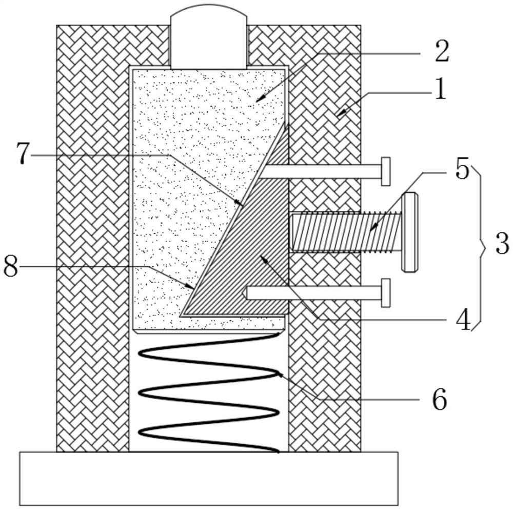
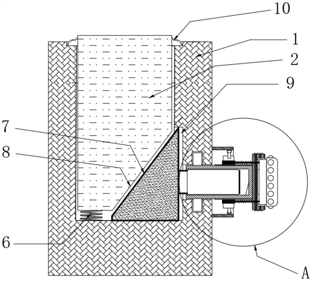
[0034] see Figure 1-8 The embodiment of the present invention provides a support mechanism for the machining center of the engine casing, including a sleeve 1 and a pillar 2, the pillar 2 is movably socketed in the sleeve 1, and the top of the pillar 2 is used to support the center of the engine casing position, the sleeve 1 and the pillar 2 are also connected by a spring 6, and also include a support assembly 3, and the support adjustment assembly 3 includes:

[0035] Inclined block 4, which has a first support inclined plane 7;

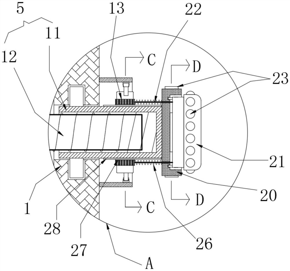
[0036] Adjusting rod 5, which is screwed with sleeve 1;

[0037] The rotation of the adjustment rod 5 drives the ramp block 4 so that the first support ramp 7 and the second support ramp 8 on the pillar 2 wedge-shap...


PUM


Abstract

The invention discloses a center part supporting mechanism and a machining fixing device of an engine shell, and relates to the technical field of machining. The center part supporting mechanism comprises a sleeve and a supporting column, the supporting column is movably connected into the sleeve in a sleeved manner, the top of the supporting column is used for supporting the center part of the engine shell, and the sleeve and the supporting column are further connected through a spring; and the center part supporting mechanism further comprises a supporting assembly, the supporting adjusting assembly comprises an inclined plane block and an adjusting rod, the inclined plane block is provided with a first supporting inclined plane, the adjusting rod is in threaded connection with the sleeve, and the adjusting rod rotates to drive the inclined plane block so that a first supporting inclined plane can be matched with a second supporting inclined plane on the supporting column in a wedge-shaped manner to achieve supporting. According to the center part supporting mechanism, the center part of the engine shell can be supported in a matched manner, good adaptability is achieved, the situation that a thin part of the center part of the engine shell is prone to inward concave deformation during machining is prevented, and meanwhile, the problem that an existing thread supporting mechanism is prone to loosening during machining high-frequency vibration is effectively solved.

Description

technical field [0001] The invention relates to the technical field of mechanical processing, in particular to a central part support mechanism and a machining fixing device for an engine casing. Background technique [0002] Machining refers to the process of changing the shape or performance of the workpiece through a mechanical device. Some engine casing machines often need to be machined through a machining center. The shell is supported. [0003] In order to avoid the vibration of the engine casing due to the milling force and prevent the parts from being deformed during processing, the existing Chinese patent announcement number is: CN209304117U. The patent includes a bolt at one end of the spacer; the bracket is an L-shaped structure in cross section, and the two sides of the L-shaped structure of the bracket are perpendicular to each other; one side is horizontal and the other is vertical; There is a through slot, the bolt of the spacer can be inserted into the thr...

Claims


Application Information

Patent Timeline
Patent Type & Authority Applications(China)
IPC IPC(8): B23Q3/06B24B41/06
CPCB23Q3/062B24B41/06
Inventor 吴南波解华文
Owner QUANJIAO LANBO ELECTROMECHANICAL
Why Eureka
Try Eureka