Eureka AIR delivers breakthrough ideas for toughest innovation challenges, trusted by R&D personnel around the world.

Projection device for realizing long-distance high-definition projection

A projection device and long-distance technology, applied in projection devices, optics, instruments, etc., can solve problems such as poor heat dissipation of projectors, inability to adapt to different projection environments, unclear aperture, etc., to achieve accurate results

Pending Publication Date: 2021-08-03
陕西光大照明电器有限公司
View PDF0 Cites 3 Cited by
  • Summary
  • Abstract
  • Description
  • Claims
  • Application Information

AI Technical Summary

Problems solved by technology

[0005] Aiming at the deficiencies of the prior art, the present invention provides a projection device for realizing long-distance high-definition projection, which solves the above-mentioned problem that there is only one set of projector lenses, and there will be unclear and aperture problems for long-distance projection. It cannot adapt to different projection environments. At the same time, the projector is hoisted on the roof. The position of the projector is fixed after hoisting, and the projection angle cannot be adjusted during use. The buckle is used to fix the connection, and it is difficult to open the projector cover, which is very inconvenient for projector cleaning and maintenance. At the same time, the integrated projector has poor heat dissipation. After continuous use, the internal heat of the projector is serious and cannot be used for a long time.

Method used

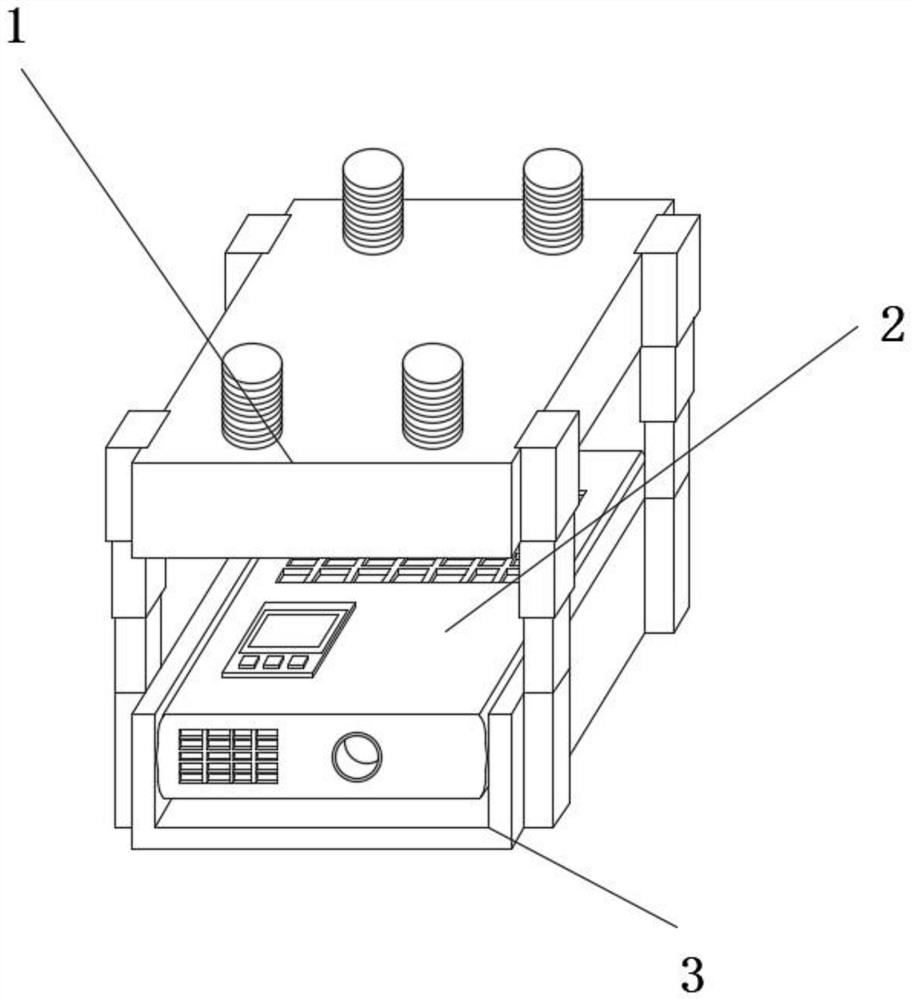

Image

  • Projection device for realizing long-distance high-definition projection
  • Projection device for realizing long-distance high-definition projection
  • Projection device for realizing long-distance high-definition projection

Examples


Embodiment Construction

[0032] Embodiments of the present invention are described in detail below, examples of which are shown in the drawings, wherein the same or similar reference numerals denote the same or similar elements or elements having the same or similar functions throughout. The embodiments described below by referring to the figures are exemplary only for explaining the present invention and should not be construed as limiting the present invention.

[0033] In describing the present invention, it should be understood that the terms "center", "longitudinal", "transverse", "length", "width", "thickness", "upper", "lower", "front", " Orientation indicated by rear, left, right, vertical, horizontal, top, bottom, inside, outside, clockwise, counterclockwise, etc. The positional relationship is based on the orientation or positional relationship shown in the drawings, which is only for the convenience of describing the present invention and simplifying the description, rather than indicating ...


PUM


Abstract

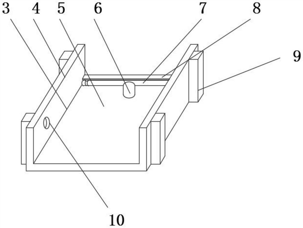
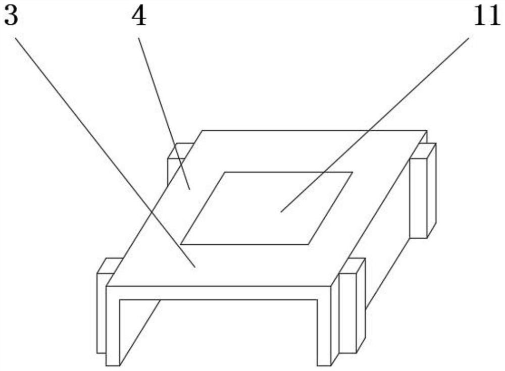
The invention provides a projection device for realizing long-distance high-definition projection, which comprises a projector mounting mechanism, the projector mounting mechanism comprises a mounting box, a mounting groove, an electric lifting rod, a horizontal shaft, an adjusting plate, a fixed block, a rotating groove and an LED lamp, the mounting groove is formed in the upper end surface of the mounting box, one end of the electric lifting rod is fixedly connected to the rear side of the bottom of the mounting groove, the horizontal shaft is fixedly connected to the end, away from the mounting groove, of the electric lifting rod, the adjusting plate is rotationally connected to the side end face of the horizontal shaft, and the two sets of rotating grooves are symmetrically formed in the inner walls of the two sides of the mounting groove; the four sets of fixing blocks are symmetrically and fixedly connected to the side end faces of the two sides of the installation box, the LED lamp is installed on the lower end face of the installation box, and a projector is installed in the projector installation mechanism. The remote projection capacity of the projector is effectively improved, meanwhile, the heat dissipation performance of the projector is improved, the storage capacity is improved, and the projector is more convenient to use and more beautiful.

Description

technical field [0001] The invention relates to the field of optical projection equipment, in particular to a projection device for realizing long-distance high-definition projection and a method for using the same. Background technique [0002] A projector, also known as a projector, is a device that can project images or videos onto a screen. It can be connected to a computer, VCD, DVD, BD, game console, DV, etc. through different interfaces to play the corresponding video signal. [0003] The current projector lens only has one set, which will cause unclear and aperture problems for long-distance projection, and cannot adapt to different projection environments. At the same time, the projector is hoisted on the roof. After the projector is hoisted, its position is fixed, and the projection angle cannot be adjusted during use. The hanger in the room will make people feel depressed and destroy the beauty of the room. Moreover, the overall structure of the existing projector...

Claims


Application Information

Patent Timeline
Patent Type & Authority Applications(China)
IPC IPC(8): G03B21/54G03B21/16G03B21/14F16M13/02F16M11/18F16M11/10F16M11/04
CPCG03B21/54G03B21/142G03B21/145G03B21/16F16M13/02F16M11/046F16M11/10F16M11/18
Inventor 李源赵栋
Owner 陕西光大照明电器有限公司
Why Eureka
Eureka Blog
Learn More