
Deceleration strip with speed measurement function

A technology of speed bumps and functions, which is applied in the field of speed bumps with a speed measurement function, and can solve problems such as poor road driving experience, bumpy feeling, and speed bumps that cannot change the height of the bulge.

Inactive Publication Date: 2021-08-06
刘立天
View PDF0 Cites 0 Cited by
  • Summary
  • Abstract
  • Description
  • Claims
  • Application Information

AI Technical Summary

Problems solved by technology

The invention is mainly used to solve the problem that the height of the bulge cannot be changed after the installation of the traditional deceleration belt, which results in a sense of bumps no matter how much the driving speed passes, which in turn causes the problem of poor road driving experience

Method used


Image

  • Deceleration strip with speed measurement function
  • Deceleration strip with speed measurement function
  • Deceleration strip with speed measurement function

Examples


Embodiment Construction

[0034] In order to make the technical means, creative features, goals and effects achieved by the present invention easy to understand, the present invention will be further described below in conjunction with specific embodiments.

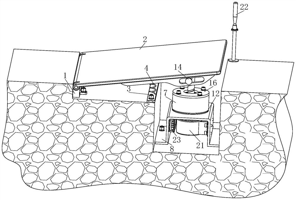
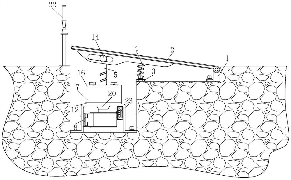
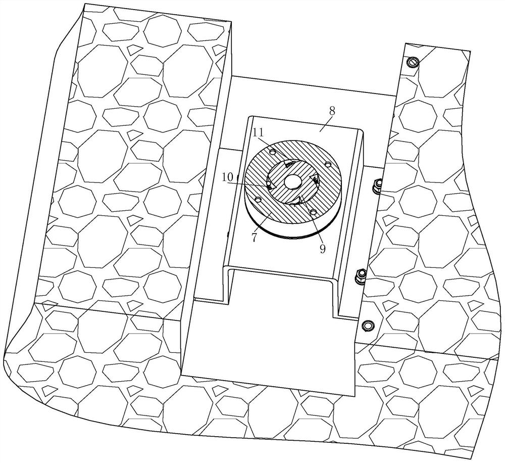
[0035] Such as Figure 1 to Figure 7As shown, a deceleration belt with a speed measurement function includes a fixed seat 1, a panel 2, a fixed strip 3, a No. 1 spring 4, a power conversion part 5, a clutch part 6, an outer ring 7 and a mounting frame 8; The seat 1 is arranged inside the groove of the road surface; the fixed seat 1 is fixedly connected with the road surface; the upper part of the fixed seat 1 is provided with the panel 2; one end of the panel 2 is rotationally connected with the fixed seat 1; Described road surface groove interior is provided with described fixed bar 3; Described fixed bar 3 is fixedly connected with described road surface; Described fixed bar 3 top symmetrically is provided with described No. 1 spring 4; One end ...


PUM


Abstract

The invention belongs to the technical field of municipal engineering and particularly relates to a speed bump with a speed measuring function. The speed bump comprises a fixed seat, a panel, a fixed strip, a first spring, a power conversion component, a clutch component, an outer ring and a mounting frame. The speed bump is advantaged in that the panel is arranged to be in a rotating connection mode, different responses are made according to different vehicle speeds, when the vehicle speed is high, impact force enables the panel to rotate downwards, then the impact force is transmitted to the clutch component, the outer ring is driven, friction of the outer ring is large, rotation of the panel is hindered, when the panel is not rotated to be flush with the road surface, a vehicle passes through the panel, so the vehicle has an obvious bumping feeling; when the vehicle speed is low, the impact force on the clutch component is small, the clutch component and the outer ring are disconnected, the panel is not affected by the rotation resistance of the outer ring in the downward rotation process, the panel can rotate to be flush with the road surface, therefore, the bumping feeling of the vehicle passing at a low speed is small, and then driving experience feeling of the vehicle driving at a low speed is good.

Description

technical field [0001] The invention belongs to the technical field of municipal engineering, in particular to a speed bump with a speed measuring function. Background technique [0002] Speed ​​bumps, also called speed bumps, are traffic facilities installed on highways to slow down passing vehicles. The shape is generally strip-shaped, and also dot-shaped; the material is mainly rubber, and there are also metal; generally yellow and black are used to attract visual attention, and the road surface is slightly arched to achieve the purpose of vehicle deceleration. It is generally set at road crossings, industrial and mining enterprises, schools, residential quarters, etc. where vehicles need to slow down and where traffic accidents are likely to occur. It is a new type of special traffic safety setting for reducing the speed of motor vehicles and non-motor vehicles; deceleration The belt realizes deceleration by influencing the driver's driving psychology. When the vehicle...

Claims


Application Information

Patent Timeline
IPC IPC(8): E01F9/529G01P3/18
CPCE01F9/529G01P3/18
Inventor 刘立天
Owner 刘立天
Learn More