
A universal speed reduction device for incoming vehicles

A deceleration device and universal technology, applied in the directions of roads, buildings, road signs, etc., can solve the problems that the deceleration belt cannot achieve the speed limit effect and the effect is difficult to produce.

Active Publication Date: 2020-12-18
嘉兴方沐能源科技有限公司
View PDF4 Cites 0 Cited by
  • Summary
  • Abstract
  • Description
  • Claims
  • Application Information

AI Technical Summary

Problems solved by technology

[0003] The existing deceleration belts are belt-shaped structures, which are used in a lane to avoid the speed of vehicles coming and going. However, this type of deceleration belt can only limit the speed of vehicles coming and going in a straight line, but it is difficult for vehicles coming from other directions. Produces an effect; especially when the speed of a vehicle needs to be limited in a wide environment, common speed bumps cannot achieve the speed limit effect at all

Method used


Image

  • A universal speed reduction device for incoming vehicles
  • A universal speed reduction device for incoming vehicles
  • A universal speed reduction device for incoming vehicles

Examples


Embodiment

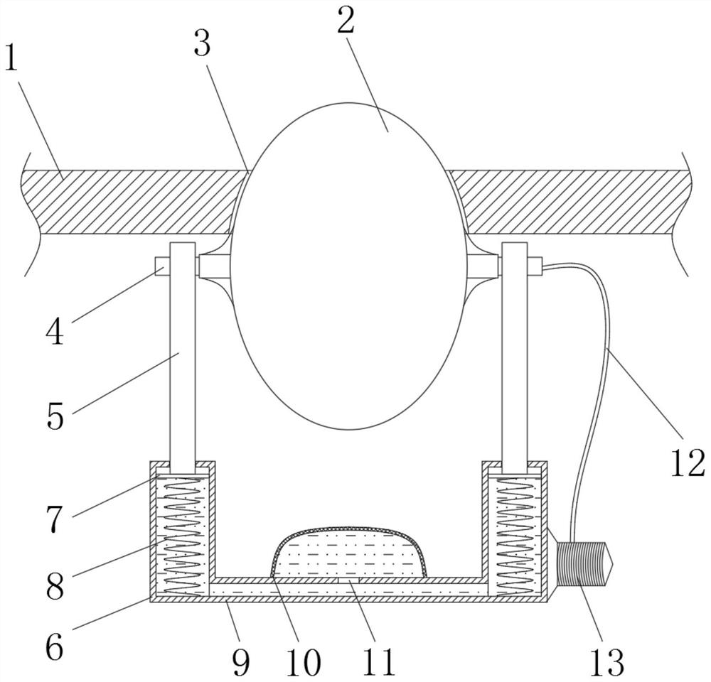
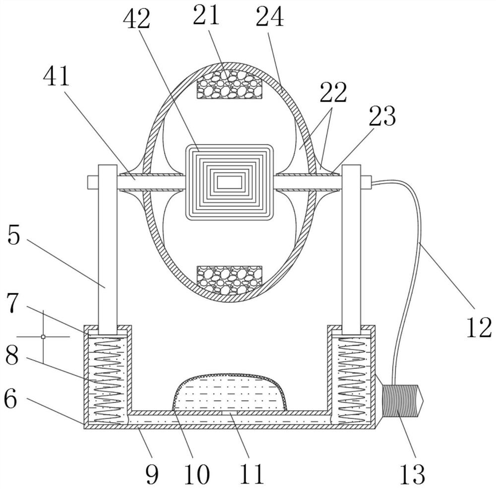
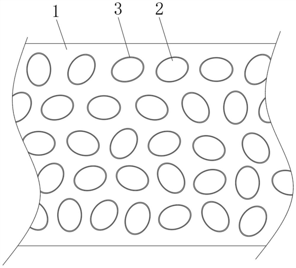
[0023] refer to Figure 1-4 , a universal oncoming vehicle deceleration device, including a floor 1 and a rotating ball 2, the floor 1 is provided with a plurality of ball holes 3, when the rotating ball 2 is at the highest point, the ball holes 3 are not in contact with the rotating ball 2, and every two There is a certain distance between two adjacent ball holes 3 to ensure that the floor between the two ball holes 3 produces enough reaction force to the wheels when the vehicle is running at a slow speed. Each ball hole 3 is provided with a The rotating ball 2 is connected to the stator 4 through a bearing, and a vertical rod 5 is fixedly connected to both ends of the stator 4, and a round tube 6 is arranged at the lower end of each vertical rod 5, and the inside of each round tube 6 There is a piston 7 in the sealing and sliding connection, and a spring 8 is fixedly connected to the lower end of each piston 7. When the vehicle passes by the rotating ball 2, the spring 8 wil...

Embodiment 2

[0034] refer to Figure 5-6 The difference between this embodiment and Embodiment 1 is that a plurality of ball grooves 25 are uniformly arranged on both sides of the outer wall reinforcement plate 22 of the ellipsoidal shell 24, and a steel ball 26 is rotatably connected in each ball groove 25, and the ball 26 It cannot fall off from the ball groove 25. When the tire of the vehicle is laterally pressed to the rotating ball 2, it can effectively reduce the torque on the rotating ball 2 and the stator 4, and reduce the possibility of damage to the rotating ball 2 and the stator 4, greatly The service life of the road section provided with the device is prolonged.

[0035] Although this article uses more floor 1, rotating ball 2, ball hole 3, stator 4, vertical rod 5, round tube 6, piston 7, spring 8, horizontal tube 9, liquid storage bag 10, through hole 11, wire 12 , Electromagnet 13, permanent magnet 21, reinforcing plate 22, through mandrel 23, ellipsoid shell 24, ball groove...


PUM


Abstract

The invention discloses a universal speed reduction device for incoming vehicles, which includes a floor and a rotating ball. The floor is provided with a plurality of ball holes, and each of the ball holes is provided with a rotating ball. The rotating ball uses a bearing and a rotating ball. The stator is rotationally connected, and both ends of the stator are fixedly connected with a vertical rod, and a circular tube is arranged at the lower end of each vertical rod, and a piston is sealed and slidably connected inside each circular tube. A spring is fixedly connected to the lower ends of each of the pistons, and one end of the spring away from the corresponding piston is fixedly connected to the bottom of the circular tube. The advantage is that when the vehicle is running at a slow speed on the road equipped with this device, the rotation speed of the wheel is too slow to drive the rotating ball to rotate at a high speed, and thus the coil cannot generate a strong current. At this time, the wheel can easily press the rotating ball To be flush with the floor, the wheels are in contact with the floor to ensure that the vehicle can run normally without bumpy discomfort.

Description

technical field [0001] The invention relates to the technical field of interior decoration, in particular to a universal speed reduction device for incoming vehicles. Background technique [0002] Speed ​​bumps are common devices on urban roads. They are generally installed on highway crossings, industrial and mining enterprises, schools, residential quarters, etc., where vehicles need to slow down and where traffic accidents are likely to occur. They are used to reduce the speed of motor vehicles and non-motor vehicles. New traffic-specific safety facilities for driving speed; [0003] The existing deceleration belts are belt-shaped structures, which are used in a lane to avoid the speed of vehicles coming and going. However, this type of deceleration belt can only limit the speed of vehicles coming and going in a straight line, but it is difficult for vehicles coming from other directions. Produces an effect; especially in a wide environment where the speed limit needs to...

Claims


Application Information

Patent Timeline
Patent Type & Authority Patents(China)
IPC IPC(8): E01F9/529
Inventor 黄珍
Owner 嘉兴方沐能源科技有限公司
Learn More