
Locomotive drive-by-wire chassis frame structure

A chassis frame, wire-controlled technology, applied in the substructure, suspension, elastic suspension and other directions, can solve the problems of water seepage in the car, the feasibility impact is very large, etc., to avoid water seepage, improve the driving experience, The effect of increasing the steering angle

Inactive Publication Date: 2020-12-18
YANCHENG INST OF TECH +1
View PDF5 Cites 1 Cited by
  • Summary
  • Abstract
  • Description
  • Claims
  • Application Information

AI Technical Summary

Problems solved by technology

[0002] The frame is a frame structure spanning the front and rear axles of the car, commonly known as the girder. The frame must have sufficient strength and rigidity to withstand the load of the car and the impact from the wheels. The function of the frame is to support and connect the various assemblies of the car, so that each assembly maintains a relatively correct position, and bears the load inside and outside the car. The main function of the frame is to bear the weight of the chassis. The weight of the frame has a great relationship with the driving performance. The current development situation shows the importance of frame optimization and the rational design of the chassis structure. The feasibility analysis of the chassis has a great impact on the vehicle, and the existing frame is likely to cause water seepage in the car when driving on the water-logged road. Therefore, the design is practical and can avoid water seepage. A locomotive by wire chassis frame structure is necessary

Method used


Image

  • Locomotive drive-by-wire chassis frame structure
  • Locomotive drive-by-wire chassis frame structure
  • Locomotive drive-by-wire chassis frame structure

Examples


Embodiment Construction

[0025] The following will clearly and completely describe the technical solutions in the embodiments of the present invention with reference to the accompanying drawings in the embodiments of the present invention. Obviously, the described embodiments are only some, not all, embodiments of the present invention. Based on the embodiments of the present invention, all other embodiments obtained by persons of ordinary skill in the art without making creative efforts belong to the protection scope of the present invention.

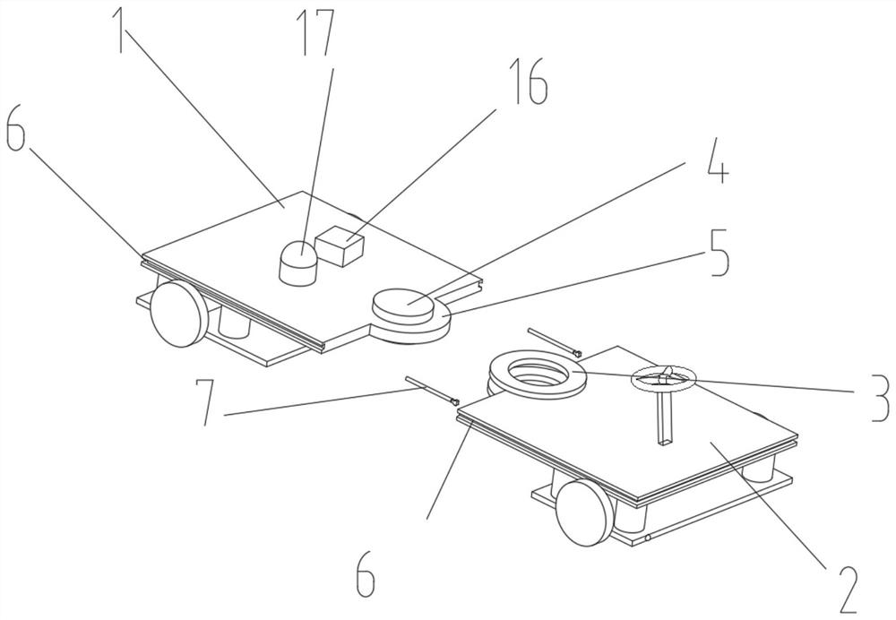
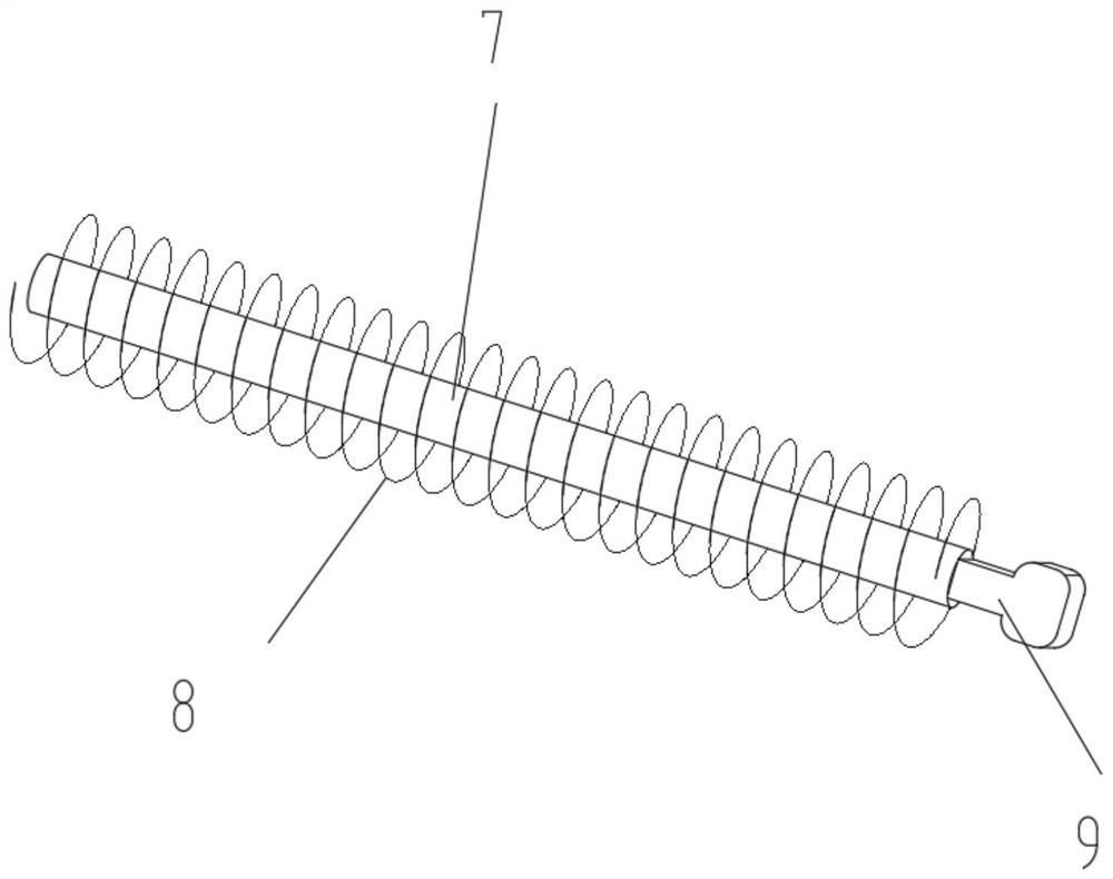
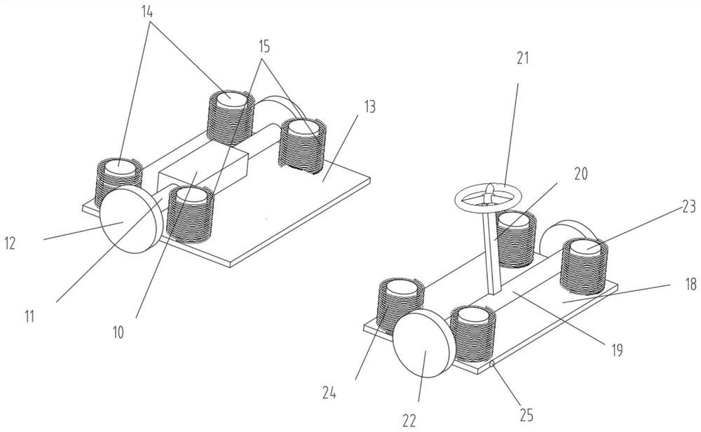
[0026] see Figure 1-4 , the present invention provides a technical solution: a locomotive by wire chassis frame structure, including a front frame 2, characterized in that: the front end of the front frame 2 is equipped with a steering transmission rod 20, and the top of the steering transmission rod 20 is equipped with a steering wheel 21 The end of the steering transmission rod 20 is connected with a steering connection shaft 19, and steering wheels 22 are ...


PUM


Abstract

The invention discloses a locomotive drive-by-wire chassis frame structure which comprises a front frame. The locomotive drive-by-wire chassis frame structure is characterized in that a steering transmission rod is installed at the front end of the front frame, a steering wheel is installed at the top of the steering transmission rod, a steering connecting shaft is connected to the tail end of thesteering transmission rod, steering wheels are installed on the two sides of the steering connecting shaft respectively, front shock-proof connecting shafts are evenly installed at the bottom of thefront frame, front shock-proof springs are connected to the surfaces of the front shock-proof connecting shafts, a front shock-proof frame is connected to the tail ends of the front shock-proof connecting shafts, a bearing sleeve is installed at the rear end of the front frame, a bearing disc is installed in the bearing sleeve, a connecting bearing is installed in the middle of the bearing disc the connecting bearing and the bearing sleeve are of a matched structure, a rear frame is installed on one side of the bearing disc, a controller is installed on the surface of the rear frame, and the controller is electrically connected with a frame telescopic connecting shaft. The locomotive drive-by-wire chassis frame structure has the advantages of being high in practicability and capable of avoiding water seepage.

Description

technical field [0001] The invention relates to the technical field of a frame structure of a locomotive controlled by wire chassis, in particular to a frame structure of a controlled by wire chassis of a locomotive. Background technique [0002] The frame is a frame structure spanning the front and rear axles of the car, commonly known as the girder. The frame must have sufficient strength and rigidity to withstand the load of the car and the impact from the wheels. The function of the frame is to support and connect the various assemblies of the car, so that each assembly maintains a relatively correct position, and bears the load inside and outside the car. The main function of the frame is to bear the weight of the chassis. The weight of the frame has a great relationship with the driving performance. The current development situation shows the importance of frame optimization and the rational design of the chassis structure. The feasibility analysis of the chassis has ...

Claims


Application Information

Patent Timeline
Patent Type & Authority Applications(China)
IPC IPC(8): B62D21/00B62D3/02B60G11/16
CPCB62D21/00B62D3/02B60G11/16
Inventor 刘玮郭俊陈勇耿龙伟林鑫焱王辉徐忠华万益东经成程锦
Owner YANCHENG INST OF TECH
Learn More