Electric heating floor

A technology of electric heating and flooring, which is applied in the field of electric heating floors, can solve problems such as not being able to meet individual heating needs, floor displacement, friction between heating equipment and floors, and achieve the effects of easy replacement, reduced shaking, and reduced friction

Pending Publication Date: 2021-09-03
柳斯文
View PDF9 Cites 0 Cited by
  • Summary
  • Abstract
  • Description
  • Claims
  • Application Information

AI Technical Summary

Problems solved by technology

[0005] The purpose of the present invention is to provide an electric heating floor to solve the problems of displacement of the floor, mutual friction between the heating equipment and the floor, and failure to meet individual heating needs in the background technology

Method used


Image

  • Electric heating floor
  • Electric heating floor
  • Electric heating floor

Examples


Embodiment Construction

[0032] The technical solutions in the embodiments of the present invention will be clearly and completely described below with reference to the accompanying drawings in the embodiments of the present invention. Obviously, the described embodiments are only a part of the embodiments of the present invention, but not all of the embodiments. Based on the embodiments of the present invention, all other embodiments obtained by those of ordinary skill in the art without creative efforts shall fall within the protection scope of the present invention.

[0033] see Figure 1 to Figure 5 , the present invention provides a technical solution:

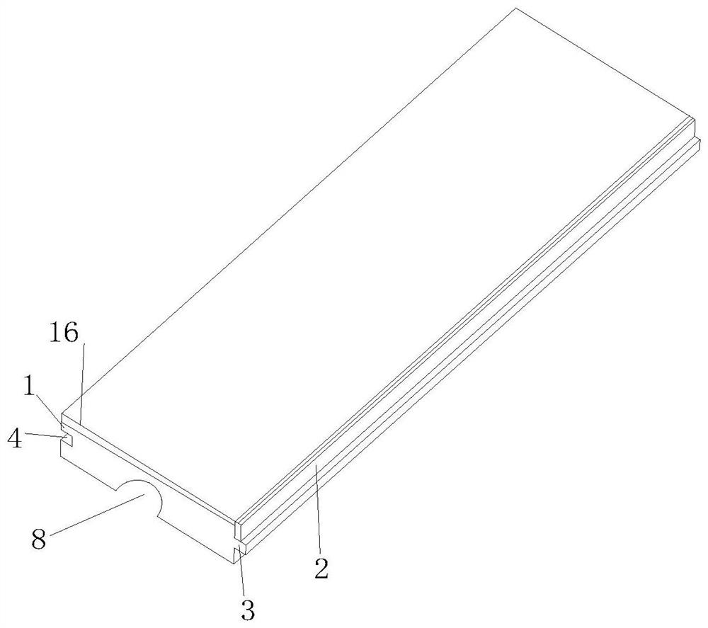
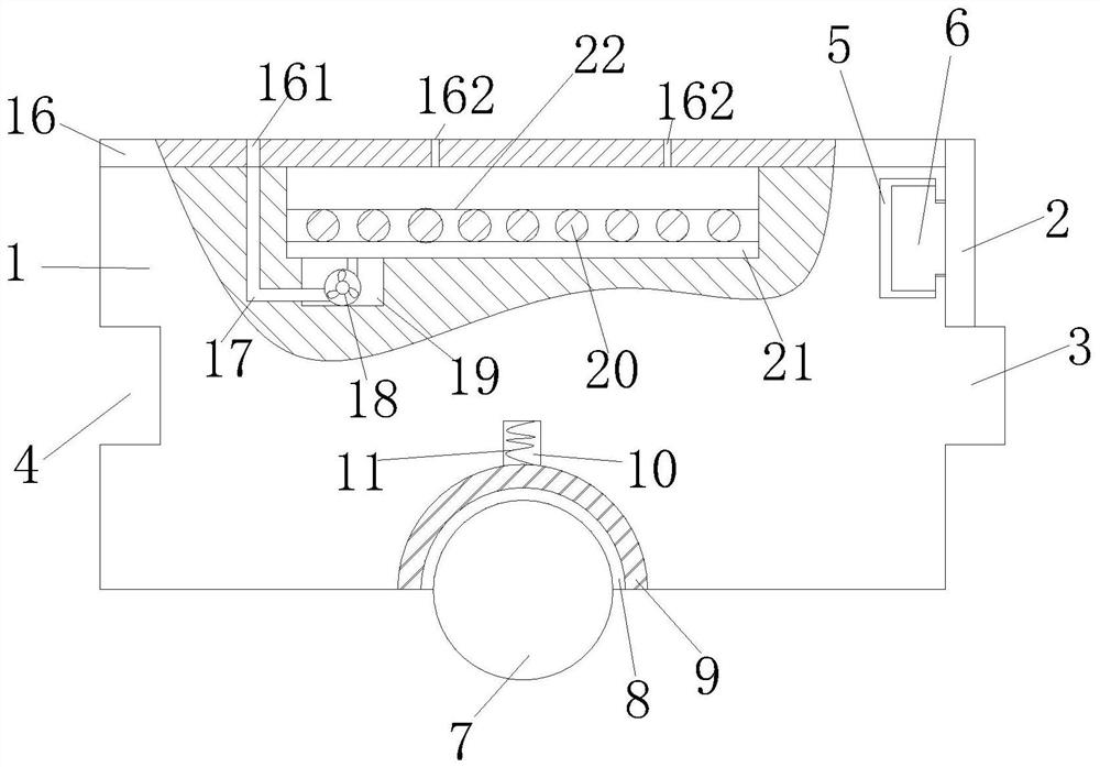
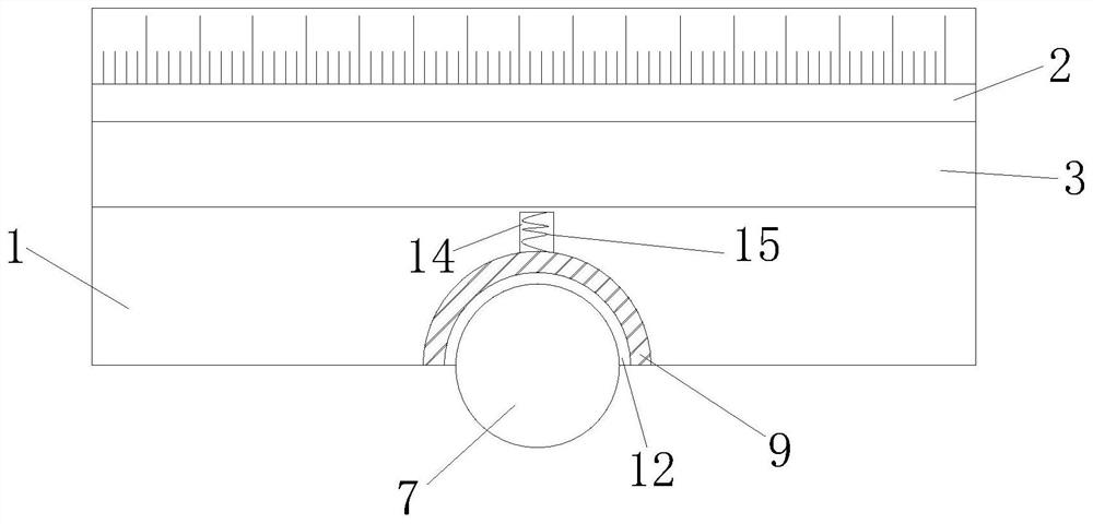
[0034] like Figure 1 to Figure 5As shown in the figure, an electric heating floor includes a floor body 1, a convex block 3 is fixedly connected in the middle of the outer surface of one side of the floor body 1, and a groove is opened in the middle of the outer surface of the other side of the floor body 1 4. A chute 5 is provided on one side...


PUM


Abstract

The invention relates to the technical field of floors, in particular to an electric heating floor which comprises a floor body and an electric auxiliary heating mechanism, a protruding block is fixedly connected to one side of the floor body, a groove is formed in the other side of the floor body, a rubber block is slidably connected to the side face of the floor body, a Z-shaped through groove is formed in the bottom face of the floor, the inner surface of the through groove is fixedly connected with sound insulation cotton; and the electric auxiliary heating mechanism comprises a resistance wire and an air blower, and the electric auxiliary heating mechanism is used for supplying heat temporarily. The splicing problem of the floor body can be well solved through the elastic rubber block, friction between a heating pipeline and the floor body can be reduced through a series of structures such as the sound insulation cotton, the heating pipeline can be fixed, sound and shaking generated when water flow passes through the heating pipeline can be reduced, and a room can be temporarily heated through the resistance wire and the air blower.

Description

technical field [0001] The invention relates to the field of floor technology, in particular to an electric heating floor. Background technique [0002] The floor, that is, the surface layer of the ground or floor of the house, is made of wood or other materials, and it is beautiful and durable. It is comfortable and natural to live in, warm in winter and cool in summer, and can well express a person's life quality. With the improvement of people's living standards, the demand for heating is getting higher and higher. [0003] In the process of realizing the present invention, the inventor found that at least the following problems in the prior art have not been solved: 1. In daily life, due to the change of temperature caused by the change of seasons, the wood floor will expand with heat and contract with cold. People walking on the floor will cause the floor to shift. Over time, the laid floor will have gaps or warps. Water or dust will enter the gaps, which will not only...

Claims


Application Information

Patent Timeline
Patent Type & Authority Applications(China)
IPC IPC(8): E04F15/02E04F15/18E04F15/20E04F15/22F24D13/02
CPCE04F15/02038E04F15/02016E04F15/181E04F15/20E04F15/225F24D13/024E04F2290/023E04F2290/041Y02B30/00
Inventor 柳斯文卢芒
Owner 柳斯文
Why Eureka
Try Eureka