Packaging equipment for capacitor production

A technology for packaging equipment and capacitors, applied in the field of capacitors, which can solve the problems of electrolyte injection, waste, electrolyte volatilization, etc.

Active Publication Date: 2021-09-14
南通海美电子有限公司
View PDF17 Cites 1 Cited by
  • Summary
  • Abstract
  • Description
  • Claims
  • Application Information

AI Technical Summary

Problems solved by technology

[0005] 1. This solution uses an air conditioner to achieve cooling. However, the air conditioner will vibrate slightly during operation, and when the output cold air of the air conditioner flows rapidly in the air pipe, it is easy to cause the bracket to vibrate, which will affect the injection of electrolyte when the capacitor is packaged;
[0006] 2. It is inconvenient to manually control the opening and closing of the air conditioner. When the fixing clip is out of contact with the capacitor, the air conditioner continues to work, resulting in waste;
[0007] 3. This solution only cools the contact between the fixing clip and the capacitor. However, there will still be heat conduction at the contact between the bottom of the capacitor and the case, causing the electrolyte to volatilize.

Method used


Image

  • Packaging equipment for capacitor production
  • Packaging equipment for capacitor production
  • Packaging equipment for capacitor production

Examples


Embodiment 1

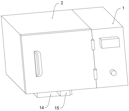
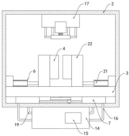
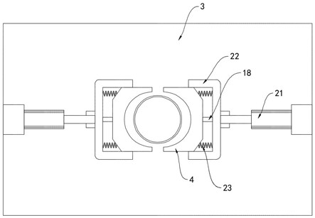
[0033] Such as Figure 1-7 As shown, a kind of packaging equipment for capacitor production includes a control box 1, a refrigeration packaging box 2 and a filler 17. A power supply is installed in the control box 1, and a switch for controlling the opening and closing of the power supply is arranged on the outer wall. The filler 17 is installed On the inner top surface of the refrigeration packing box 2, a horizontal plate 3 is installed in the refrigeration packing box 2, and two fixing blocks 4 are arranged on the As for the fixing mechanism 6 for fixing the capacitor, a cooling mechanism 7 for cooling the capacitor is provided under the horizontal plate 3;

[0034] Further, the cooling mechanism 7 includes a turntable 8 and two liquid inlet cylinders 9, and a piston 10 is sealed and slid in the two liquid inlet cylinders 9, and the two pistons 10 are fixed by a connecting rod 11, and the connecting rod 11 is fixedly connected with a The swing frame 12 is slidingly connect...

Embodiment 2

[0044] Such as Figure 8 As shown, the difference between this embodiment and Embodiment 1 is that the cavity 24 is filled with low-temperature molten salt, and the liquid level of the low-temperature molten salt is lower than the rack 26. In this embodiment, pyrrole is used for the low-temperature molten salt. Salt ion type, not easy to volatilize, and has poor electrical conductivity at low temperature, and good electrical conductivity at high temperature. The upper surface of the horizontal plate 3 is equipped with an electrothermal difference sheet 31, which is made of semiconductor material. , the heat will be transferred from the hot surface to the cold surface, the cold surface of the electrothermal plate 31 faces upwards, the hot surface is in contact with the upper surface of the horizontal plate 3, and the positive and negative poles of the electrothermal plate 31 are electrically connected to the power supply through a low-temperature molten salt .

[0045] In this...


PUM


Abstract

The invention belongs to the technical field of capacitors, and particularly relates to packaging equipment for capacitor production. The packaging equipment comprises a control box, a refrigeration packaging box and a filler, wherein a transverse plate is mounted in the refrigeration packaging box, two fixing blocks are arranged on the transverse plate, a cooling liquid cavity is formed in each fixing block, a fixing mechanism for fixing a capacitor is arranged on the transverse plate, and a cooling mechanism for cooling the capacitor is arranged below the transverse plate; and the cooling mechanism comprises a rotating disc and two liquid inlet cylinders, pistons are arranged in the two liquid inlet cylinders respectively in a sealed and sliding mode, the two pistons are fixed through a connecting rod, and a swing frame is fixedly connected to the connecting rod. According to the packaging equipment, cooling liquid can be pumped into the cooling liquid cavity through the liquid inlet cylinders, so that a good cooling effect is achieved; compared with the prior art, vibration generated during the flowing of the cooling liquid is slight, and the influence on the packaging work of the capacitor is avoided; and the cooling effect is further achieved through contact between the cold face of an electro-induced temperature difference piece and the bottom of the capacitor.

Description

technical field [0001] The invention belongs to the technical field of capacitors, in particular to packaging equipment for capacitor production. Background technique [0002] A capacitor is a component that can store charges, and it is also one of the most commonly used electronic components. Capacitors play an important role in tuning, bypassing, coupling, filtering and other circuits. [0003] After searching, the national patent publication number is CN 110228645 B, which discloses a capacitor packaging equipment. Its structure includes a knob, a control box, a display screen, a power switch, a box door, a hinge block, a refrigeration packaging box, a stuffing device, and the knob is embedded in the At the front of the control box, when the air conditioner is in operation, cold air will be generated, and the cold air will be transported to the embedding groove through the air pipe, and then the cold air will be transported to the arc-shaped groove through the air guide h...

Claims


Application Information

Patent Timeline
Patent Type & Authority Applications(China)
IPC IPC(8): B65B63/08B65B65/00
CPCB65B63/08B65B65/00
Inventor 邵淋锋
Owner 南通海美电子有限公司
Why Eureka
Try Eureka