

Automatically telescopic movable louver wall
Patent Information
- Authority / Receiving Office
- CN · China
- Current Assignee / Owner
- DONGGUAN BAICUIKE WINDOWS DOORS & FURNITURE
- Publication Date
- 2021-09-14
Smart Images

Figure 1 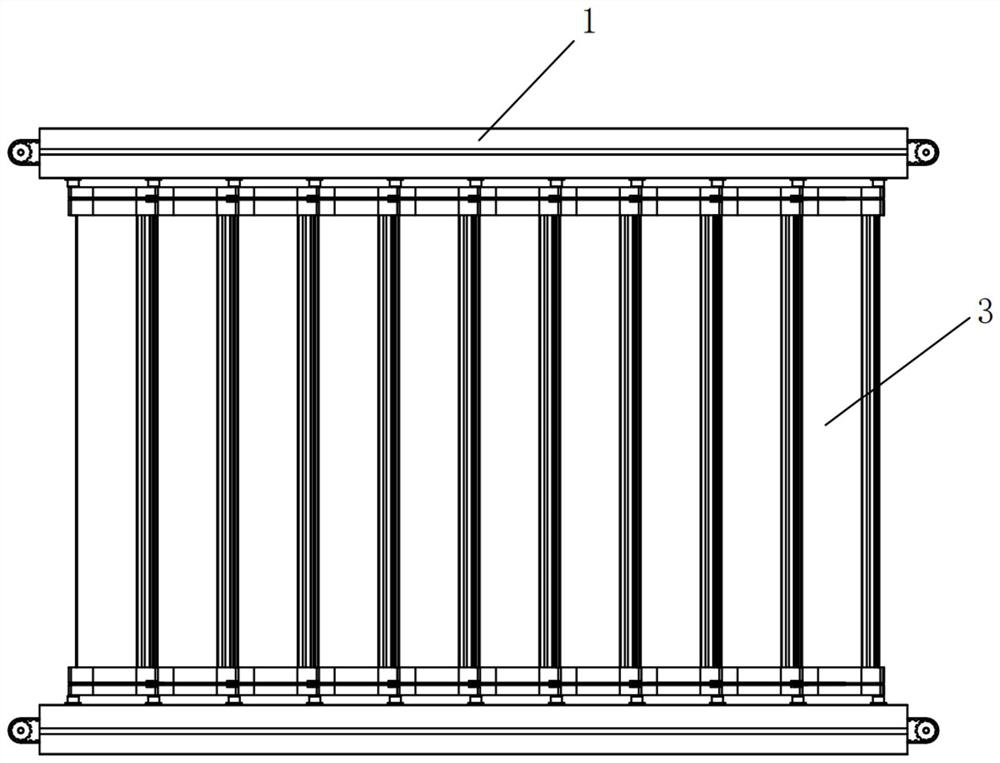
Figure 2 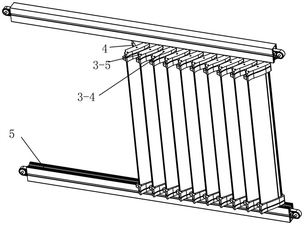
Figure 3
Abstract
Description
technical field
[0001] The invention relates to the field of automatically retractable movable louver walls. Background technique
[0002] Shutters are windows with louvers, which are generally used for indoor and outdoor sunshade and ventilation. Chinese Invention Patent Application Publication No. CN 111395934 A discloses a louver window structure, the louver window structure includes a basic frame body, the basic frame body is a hollow rectangular frame structure; a curtain flipping actuator, the The venetian blind is arranged on the upper part of the basic frame; the venetian blind is arranged in the basic frame and the upper part of the venetian blind is connected with the said venetian reversible actuator; mechanism and the venetian blind lifting internal control mechanism, the internal control mechanism for the curtain flipping is set on the right side of the basic frame and connected with the curtain flipping actuator, the internal control mechanism for the venetian...