Three-Dimensional Printing System Using Dual Rotation Axes

a three-dimensional printing and rotation axes technology, applied in additive manufacturing processes, manufacturing tools, coatings, etc., can solve the problems of high cost or difficulty of precision linear ways and drive mechanisms associated with ways, and the normal slowness of the fabrication process, so as to facilitate the movement of multiple printheads independently, the effect of simple fabrication of rotating elements and high throughpu

Active Publication Date: 2013-07-25
WISCONSIN ALUMNI RES FOUND
View PDF1 Cites 158 Cited by
  • Summary
  • Abstract
  • Description
  • Claims
  • Application Information

AI Technical Summary

Benefits of technology

[0004]The present invention provides a non-Cartesian mechanism for 3-D printing in which motion between the printhead and print surface is defined by two elements that move relatively only in rotation. The fabrication of rotating elements can be simpler than the fabrication of precision linear elements,

Problems solved by technology

Fabrication of precision linear ways and the drive mechanism associated with the ways can be costly or difficult, particularly for large or very small systems.
Further th

Method used


Image

  • Three-Dimensional Printing System Using Dual Rotation Axes
  • Three-Dimensional Printing System Using Dual Rotation Axes
  • Three-Dimensional Printing System Using Dual Rotation Axes

Examples


Embodiment Construction

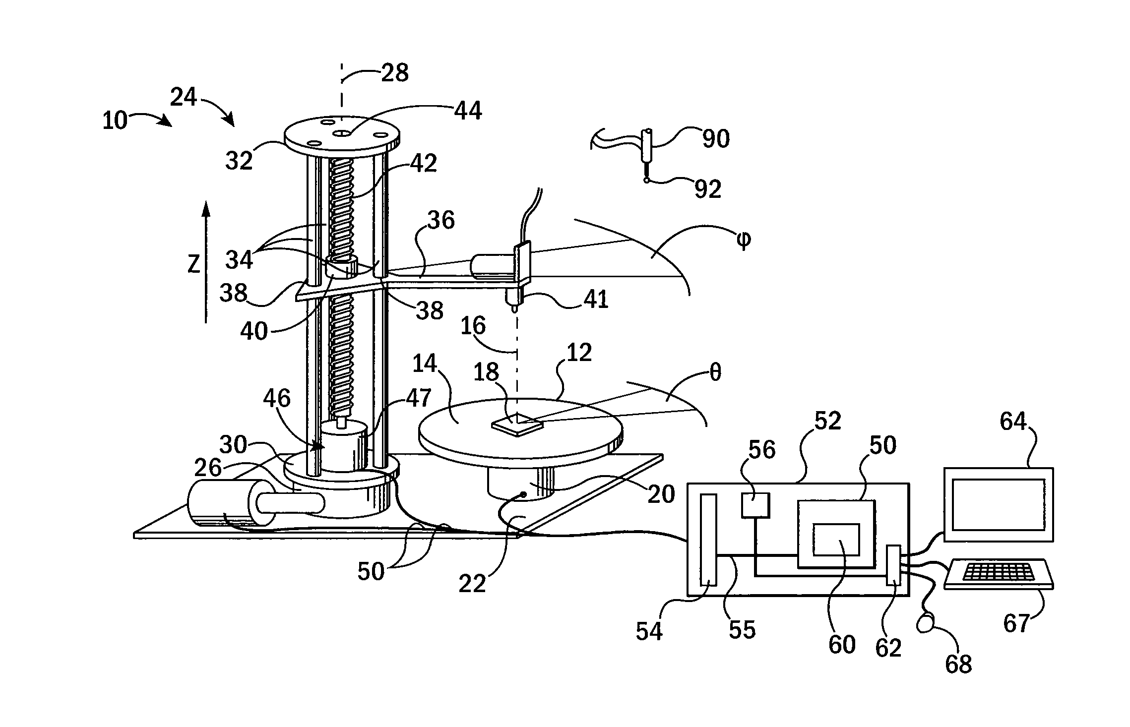
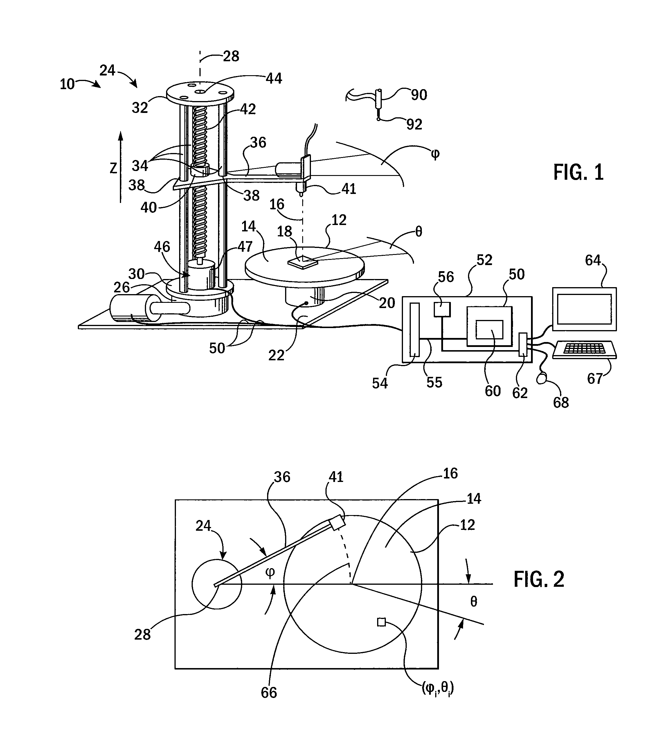
[0043]Referring now to FIG. 1, a 3-D printer 10 according to one embodiment of the present invention may provide an object platform 12 presenting a substantially upwardly facing horizontal planar surface 14. The surface 14 provides a printing area on which an object 18 may be printed and is rotatable about a vertical axis 16 indicated by angle θ.

[0044]The object platform 12 is supported on a rotary drive 20 allowing position-controlled rotation of the object platform 12 about the axis 16 under computer control. The rotary drive 20 may include, for example, bearings supporting the object platform 12 for rotation about the vertical axis 16 and a motor system, for example, a stepper motor or permanent magnet DC motor and encoder, providing for positioning. When a stepper motor is used, micro-stepping control may be implemented providing an accuracy of more than 1000 steps per revolution with direct drive. Alternatively or in addition, a gear train may be used to connect the motor to th...


PUM

PropertyMeasurementUnit
Angleaaaaaaaaaa
Volumeaaaaaaaaaa
Areaaaaaaaaaaa

Abstract

A 3-D printer system moves a printed tool over a print surface with a mechanism controlling a rotational angle of an arm holding the print tool and a revolutionary angle of axis of rotation of the printable area to eliminate the disadvantages of conventionally used linear motion mechanisms

Description

BACKGROUND OF THE INVENTION[0001]Three-dimensional (3-D) printing (also known as additive manufacturing or rapid prototyping) allows for the production of three-dimensional objects by building up a material on a layer-by-layer basis. One common 3-D printer employs a printhead extruding material and movable in three Cartesian axes (x, y, z) with respect to a print surface. Under the control of a computer, the printhead moves through a series of positions over the printing surface and at each location deposits a small volume of material to define a portion of the printed object at that location. After a base layer is printed directly on the printing surface, the printhead is successively elevated (z-axis) to print additional layers on top of the base layer and then each succeeding layer until the entire object is printed.[0002]At least one of the printhead or print surfaces is typically supported on an x-y carriage having ways extending along one axis (e.g. the x-axis) that support a ...

Claims


Application Information

Patent Timeline
IPC IPC(8): B05D1/26B05C11/00
CPCB29C67/0055B33Y30/00B29C64/118B29C64/106B29C64/188
Inventor MACKIE, THOMAS R.PATTERSON, NATHAN JAMESCOX, BENJAMIN L.SCHUMACHER, NATHAN D.PETRY, GEORGE WICKS
Owner WISCONSIN ALUMNI RES FOUND
Why Eureka
Try Eureka