Mechanisms for control knobs and other interface devices

a technology of mechanical knobs and interface devices, applied in the direction of electrical haptic/tactile feedback, instruments, computing, etc., can solve the problems of limited control options of users, limited rotary and/or push-pull knobs, and limited touch of mechanical knobs

Inactive Publication Date: 2006-05-02
IMMERSION CORPORATION
View PDF144 Cites 150 Cited by
  • Summary
  • Abstract
  • Description
  • Claims
  • Application Information

AI Technical Summary

Benefits of technology

[0006]The present invention provides a knob control interface that allows a user to control functions of a device in a variety of ways. Embodiments of the knob controller include mechanisms allowing additional degrees of freedom for the knob.
[0007]More particularly, in one embodiment a knob controller device of the present invention includes a knob rotatable in a rotary degree of freedom about an axis extending through the knob. The knob is also moveable in a lateral plane approximately perpendicular to the axis. A mechanism provides a particular lateral direction to the movement of the knob in the lateral plane. The mechanism can include a gate member and a plunger member. The plunger member engages one side of the gate member to provide the particular lateral direction. The mechanism can also include two slider members engaged to slide transversely with respect to each other and allow the movement in the lateral plane. A rotational sensor detects a position of the knob in the rotary degree of freedom and a lateral sensor detects a position of the knob in the particular lateral direction. Preferably, the gate member includes a plurality of grooves, each of the grooves corresponding with one of the predetermined lateral directions, where the plunger member engages one of the grooves. In some embodiments, the gate and plunger members are positioned offset from the axis extending through the knob, and second gate and plunger members are positioned on a different side of the axis, providing additional stability. In preferred embodiments, an actuator is coupled to the knob and outputs a force in the rotary degree of freedom about the axis.
[0010]The present invention provides a control interface device that includes greater control functionality for the user. The linear and transverse degrees of freedom of the knob allow the user to select functions, settings, modes, or options with much greater ease and without having to take his or her hand off a manipulandum such as a knob. Force feedback may also be added to the manipulandum to provide the user with greater control and to inform the user of options and selections through the sense of touch. Actuator and transmission innovations allow the manipulandum to be moved in the additional degrees of freedom, and provide little play and friction, thus enhancing the force feedback embodiments of the present invention.

Problems solved by technology

One problem occurring in control knobs of the prior art is that the knobs are limited to basic rotary and / or push-pull motion.
This limits the control options of the user to a simple device that does not allow a variety of selection options.
Most mechanical knobs have a very limited feel, i.e., they do not have the ability to feel different depending on the interface context.
In addition, if force feedback is provided on the knob, the limited control functionality of the knob limits the user from fully taking advantage of the force feedback to provide more control over desired functions.
Furthermore, many of the well-known force feedback sensations are inadequate for dealing with some of the selection functions required from a knob, where often complex control over functions and options must be provided with limited knob motion.

Method used


Image

  • Mechanisms for control knobs and other interface devices
  • Mechanisms for control knobs and other interface devices
  • Mechanisms for control knobs and other interface devices

Examples


embodiment 50

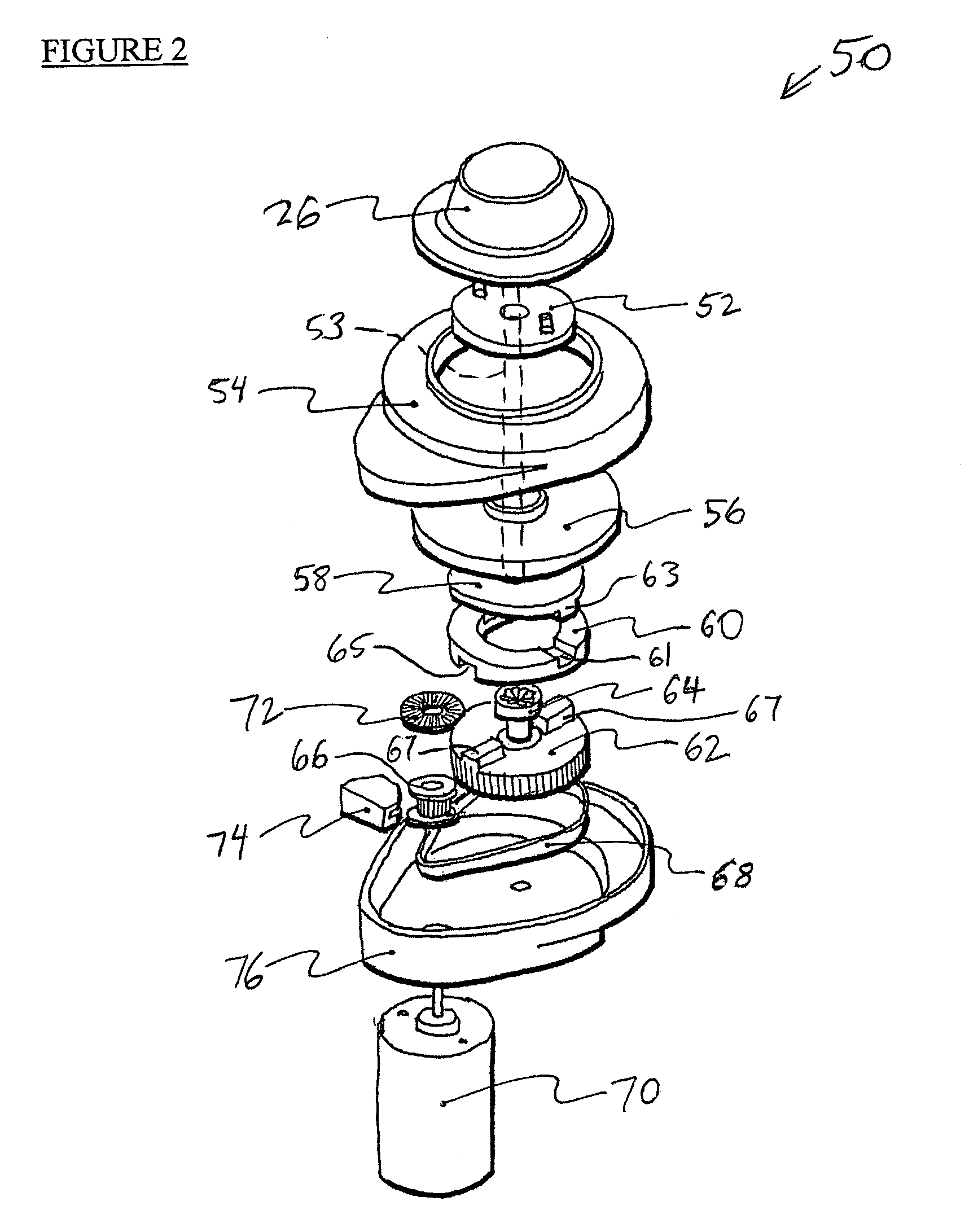
[0048]Other advantages of the embodiment 50 include a high holding torque, very scalable mechanical design, a smaller / less expensive actuator due to the use of transmission amplification, and improved encoder resolution due to the drive transmission amplification. There are some disadvantages as well: the mechanism requires significant depth in a housing to house it; there is friction inherent in the belt transmission; the drive transmission increases the device's complexity; and more joints in the moving parts result in greater backlash in the device. Furthermore, this embodiment is not as suitable for the axial-moving motor shaft invention described herein as other embodiments.

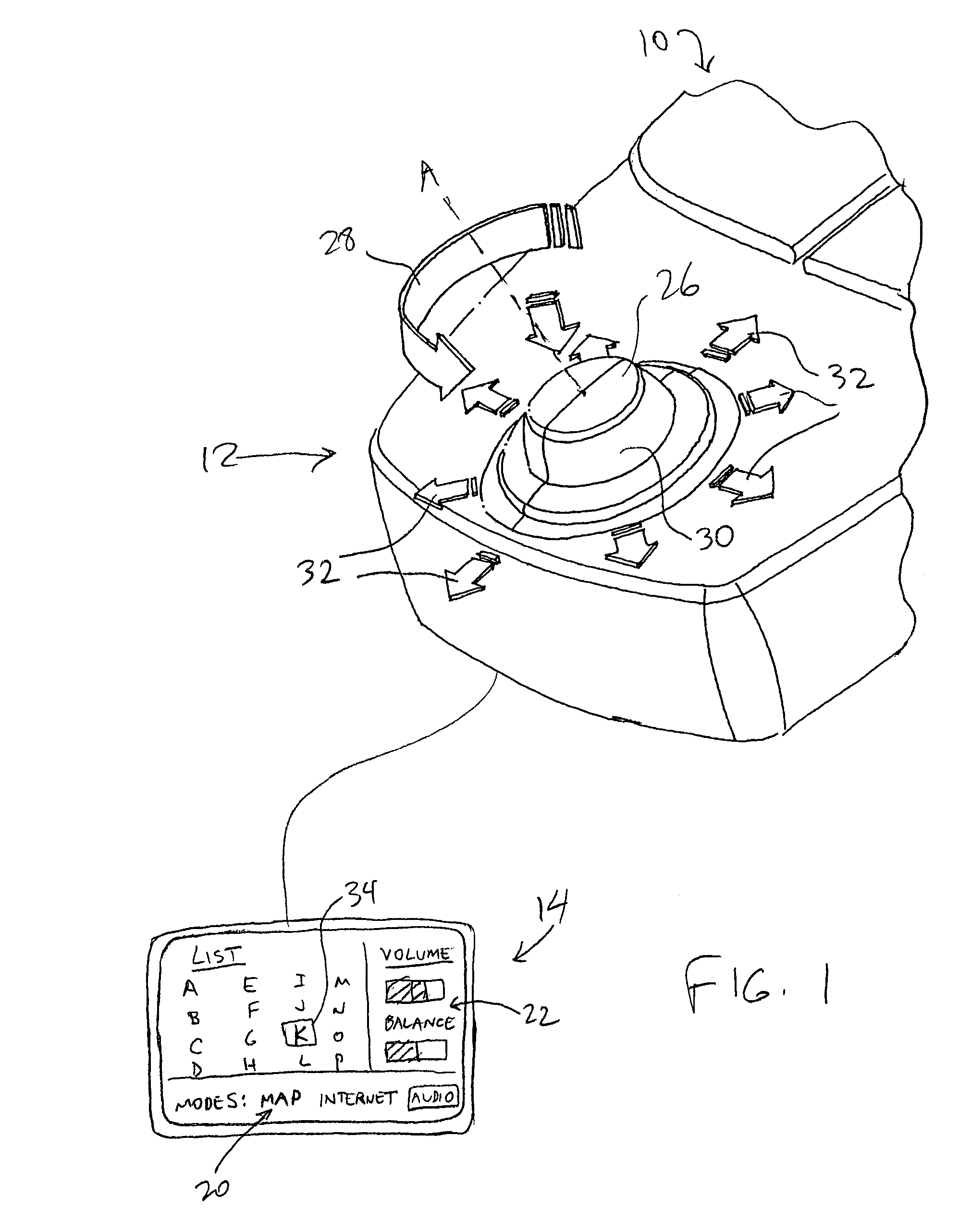
[0049]In another alternate embodiment, one or more of the transverse or lateral motions of knob 26 can be actuated. For example, a linear or rotary actuator can be provided to output forces in the transverse degree of freedom, in one or both directions (toward the center position and away from the center pos...

embodiment 230

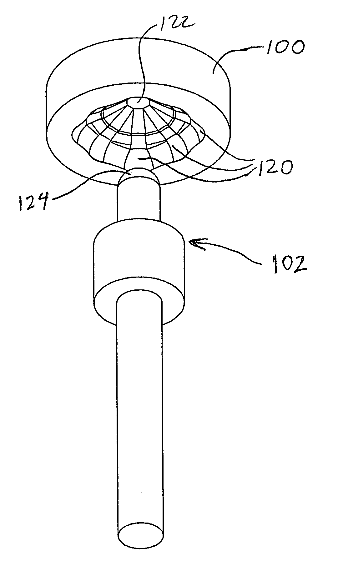
[0084]Spring 280 also allows rotational motion to be transmitted between shaft 278 and shaft 274 (and thus the knob 26 and gear 276). Spring 280 is preferably rigid in a circumferential direction and does not allow torsion flex, so that rotation of shaft 278 by actuator 282 (discussed below) is transmitted as faithfully as possible to shaft 274 and knob 26 without excessive play or compliance. Helical or other types of springs, or other couplings that allow translation and can transmit rotation, such as a bellows, a helical flexible coupling, or a splined shaft inside of a splined cavity, can be used for spring 280. In still other embodiments, no spring 280 or other coupling is provided, and shaft 278 is instead able to be moved axially with respect to the motor to allow knob axial motion, as in the embodiment 230 shown above in FIG. 6. In alternate embodiments, the motion along axis Z can be actuated by using an actuator to output forces in the linear degree of freedom, such as a l...


PUM


Abstract

Mechanisms for a control knob or other interface device providing additional degrees of freedom for the knob. One embodiment provides a rotatable knob moveable also in a lateral plane approximately perpendicular to the axis of rotation. A mechanism providing the lateral motion can include a gate member and a plunger member that engages grooves in the gate member. A rotational sensor detects a rotational position and a lateral sensor can detect a lateral position of the knob. Another embodiment provides an actuator that includes a shaft that is coaxial with the axis of rotation and which can be moved linearly along the axis of rotation with respect to actuator housing to accommodate linear motion of the knob. In another embodiment, a gear assembly including two interlocked gears is provided to transmit rotational motion from the knob to the sensor, and the interlocked gears translate with respect to each other when the knob is translated along the rotational axis.

Description

CROSS REFERENCE TO RELATED APPLICATIONS[0001]This application is a continuation-in-part of U.S. application Ser. No. 09 / 179,382, filed Oct. 26, 1998, issued on Nov. 28, 2000 as U.S. Pat. No. 6,154,201, and this application claims priority to U.S. Provisional Application Nos. 60 / 149,781, filed Aug. 18, 1999; 60 / 159,930, filed Oct. 14, 1999; and 60 / 182,557, filed Feb. 15, 2000, all of which are incorporated herein by reference.BACKGROUND OF THE INVENTION[0002]This invention relates generally to knob control devices, and more particularly to control knob devices including force feedback and / or additional input functionality.[0003]Control knobs are used for a variety of different functions on many different types of devices. Often, rotary control knobs offer a degree of control to a user that is not matched in other forms of control devices, such as button or switch controls. For example, many users prefer to use a rotating control knob to adjust the volume of audio output from a stereo...

Claims


Application Information

Patent Timeline
Patent Type & Authority Patents(United States)
IPC IPC(8): G09G5/00
CPCG06F3/016G06F3/0338G06F3/0362H01H25/06H01H25/008H01H2025/043H01H2003/008
Inventor VASSALLO, STEVEN P.MARTIN, KENNETH M.
Owner IMMERSION CORPORATION
Why Eureka
Try Eureka