Illumination control system

A technology for lighting control systems and lighting areas, applied in lighting devices, information technology support systems, power network operating system integration, etc., can solve problems such as high network switch prices, enterprise losses, lighting failures, etc., to improve safety and stability performance, good heat dissipation performance, and the effect of improving stability

Inactive Publication Date: 2011-01-12
CHINA CEC ENG
View PDF3 Cites 5 Cited by
  • Summary
  • Abstract
  • Description
  • Claims
  • Application Information

AI Technical Summary

Problems solved by technology

Therefore, many companies simply use manual methods to control lighting requirements, which inevitably leads to some problems such as energy waste caused by staff negligence.
Or, some enterprises adopt a timing on / off control method for the lamps in the controlled lighting area. However, this method is relatively mechanical and cannot flexibly turn on / off the lamps according to the actual situation in the controlled area, which may cause Such problems: that is, entering the controlled lighting area at the moment set to turn off the lights will not turn on the lights conveniently, or the light is actually sufficient at the moment set to turn on the lights, thus causing waste
In this case, if you want to control the lamps in the entire lighting area, you need to set up multiple network switches. However, the price of network switches is generally high, which will make the entire system very expensive.
In particular, the lighting control system for paper-making enterprises usually involves the separate control of multiple lighting areas, and thus requires a large number of network switches, which makes the lighting control system suitable for such enterprises expensive.
[0007] Second, the above-mentioned network switch usually needs to be installed on site. As mentioned earlier, the environment of a factory like a paper mill is very harsh, which will affect the stability of the network switch. If it causes lighting failure and affects normal production, it will give Enterprises cause a lot of unnecessary losses
[0008] Third, in the intelligent lighting control system provided by the existing technology, the control scheme has a single function, and for some lighting environments with more complex requirements, it will not be able to meet the required control requirements

Method used


Image

  • Illumination control system
  • Illumination control system
  • Illumination control system

Examples


Embodiment Construction

[0030] In order to enable those skilled in the art to better understand the technical solution of the present invention, the lighting control system provided by the present invention will be described in detail below with reference to the accompanying drawings.

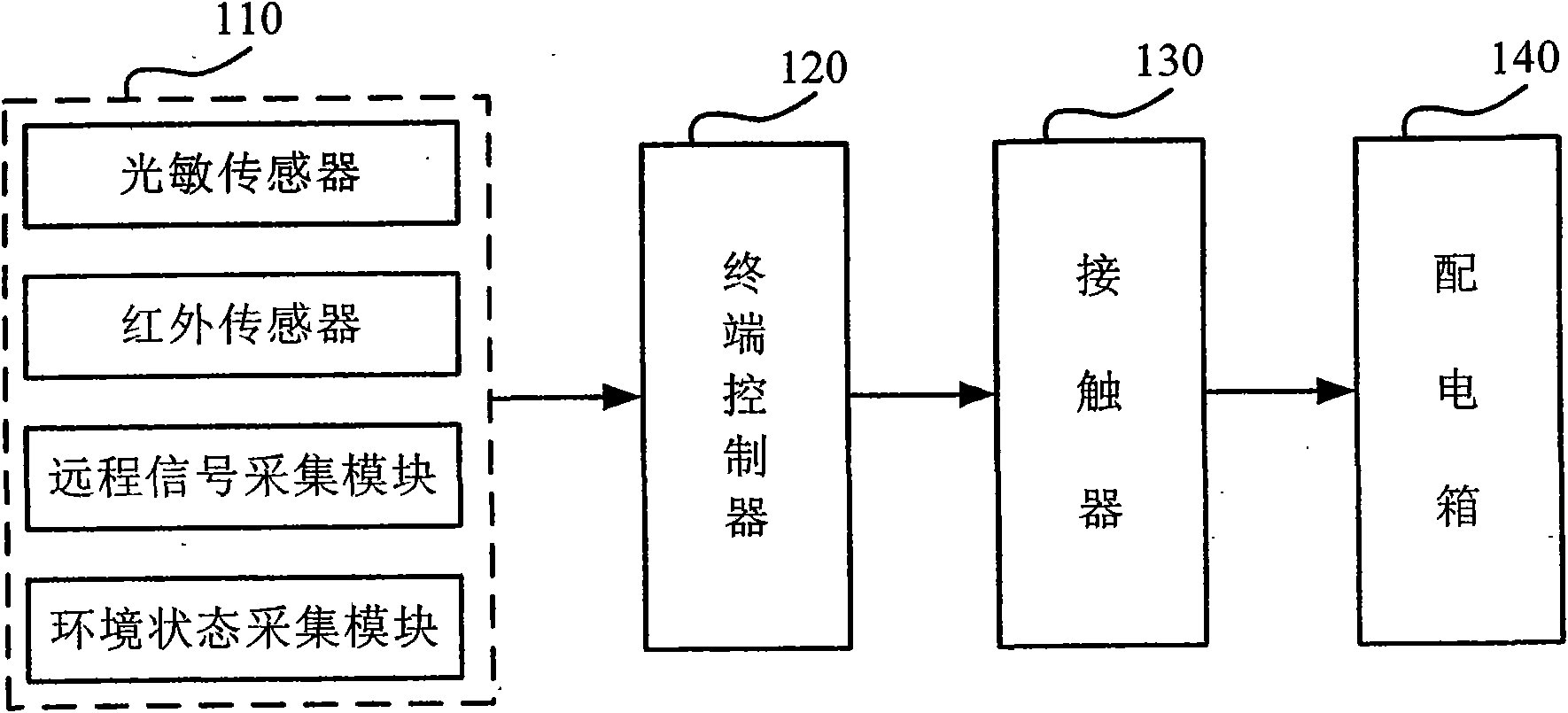
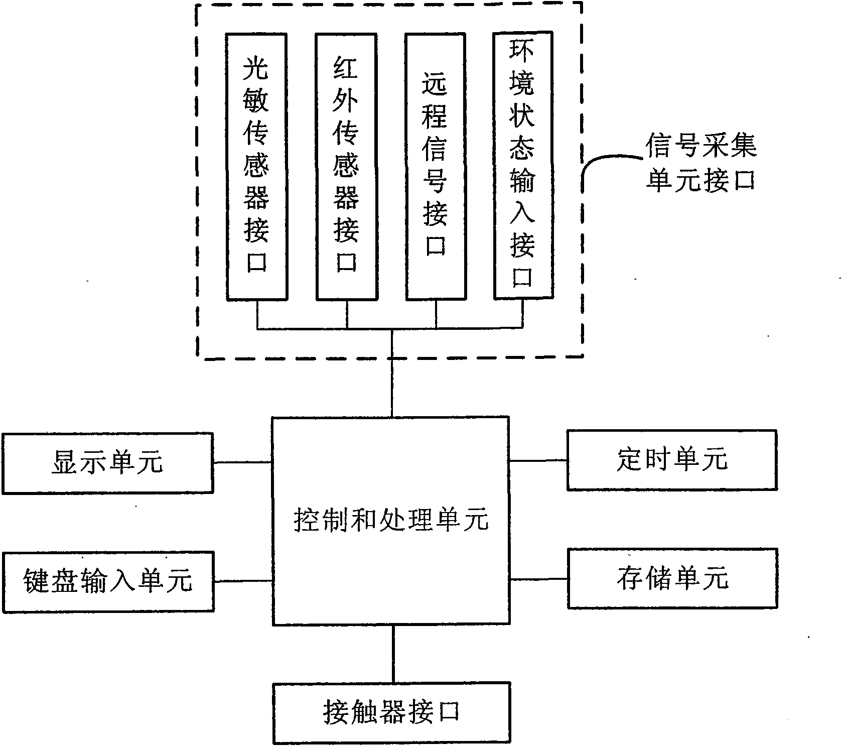
[0031] see figure 1 , The lighting control system provided by the present invention includes a signal acquisition unit 110, a terminal controller 120, a contactor 130, a distribution box 140 and a lamp (not shown) that are electrically connected to each other.

[0032]Wherein, the signal collection unit 110 is connected to the terminal controller 120 for collecting signals related to the on / off state of the contactor 130 in the controlled lighting area and transmitting them to the terminal controller 120 .

[0033] Generally, the signal acquisition unit 110 may include at least one of the following components: a photosensitive sensor, which is used to detect the brightness in the controlled lighting area, and convert ...


PUM


Abstract

The invention provides an illumination control system. The illumination control system comprises a signal acquisition unit, a terminal controller, a contactor, a distribution box and a lamp which are electrically connected, wherein the signal acquisition unit is connected with the terminal controller and is used for acquiring signals related to the on/off states of the contactor in a controlled illumination area and transmitting the signals to the terminal controller; the terminal controller is connected between the signal acquisition unit and the contactor and is used for determining the on/off states of the contactor according to the signals acquired by the signal acquisition unit and transmitting corresponding control commands to the contactor; the contactor is connected between the terminal controller and the distribution box and is used for being switched on or switched off according to the control commands so as to make the return circuits of the distribution box switched on or switched off; and the distribution box is connected between the contactor and the lamp and is used for supplying powder to the lamp connected with the distribution box in the controlled illumination area when the return circuit of the distribution box is switched on. The illumination control system has the advantages of powerful function, safety, reliability and low cost.

Description

technical field [0001] The invention relates to the technical field of lighting control, in particular to a lighting control system suitable for industrial applications. Background technique [0002] With the continuous development of industrial production, the relationship between process flow and lighting environment is becoming increasingly close; and with the increasing shortage of energy, the requirements for energy saving in industrial production are also getting higher and higher. Therefore, this requires manufacturers to control their industrial lighting more and more scientifically and efficiently. [0003] However, in actual production, the process environment and production process are often more complicated. Taking papermaking enterprises as an example, on the one hand, the air in the production workshop is corrosive due to the input of high-temperature steam, chemicals and other substances in the papermaking process, resulting in The environment in which the li...

Claims


Application Information

Patent Timeline
Patent Type & Authority Applications(China)
IPC IPC(8): H05B37/02H02J13/00
CPCY04S20/246Y02B70/3283Y02B70/30
Inventor 陈大勇
Owner CHINA CEC ENG
Why Eureka
Try Eureka