Tunnel illumination control system

A control system and technology for tunnel lighting, applied in the field of tunnel lighting, can solve the problems of inability to observe the tunnel driving environment, small brightness difference, hidden safety hazards, etc., and achieve the effects of saving lighting power, preventing visual fatigue, and saving energy

Pending Publication Date: 2021-09-21
山西省交通科技研发有限公司 +1
View PDF11 Cites 0 Cited by
  • Summary
  • Abstract
  • Description
  • Claims
  • Application Information

AI Technical Summary

Problems solved by technology

[0002] With the development of the modern highway network, more and more tunnels are becoming more and more, and the control of tunnel lighting has an increasingly important impact on road traffic safety. The lighting lamps in the existing highway tunnels all work by means of general lighting. , that is, all the lighting lamps in the tunnel work in the same working mode, that is to say, the working brightness of all the lighting lamps is the same (due to the differences between individual lighting lamps and lighting control equipment, there are brightness differences, but the brightness difference is small ), but there are serious potential safety hazards in the existing working method: if the ambient light outside the tunnel on the entrance side of the tunnel is greater than the illumination intensity inside the tunnel, then the vehicle just enters the tunnel for a short time or when it is about to enter the tunnel, the tunnel It is equivalent to a "black hole". The driver cannot observe the driving environment in the hole. If the ambient light outside the tunnel on the entrance side of the tunnel is less than the lighting intensity inside the tunnel, then the vehicle will enter the tunnel within a short time or will soon enter the tunnel. At the same time, the driver will have a glare phenomenon, and it is also impossible to observe the driving environment in the tunnel. Of course, the same phenomenon is also true at the exit side of the tunnel. one of the reasons

Method used


Image

  • Tunnel illumination control system

Examples


Embodiment Construction

[0019] The following will clearly and completely describe the technical solutions in the embodiments of the present invention with reference to the accompanying drawings in the embodiments of the present invention. Obviously, the described embodiments are only some, not all, embodiments of the present invention. Based on the embodiments of the present invention, all other embodiments obtained by persons of ordinary skill in the art without making creative efforts belong to the protection scope of the present invention.

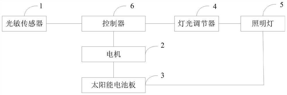
[0020] The purpose of the present invention is to provide a tunnel lighting control system, which can effectively eliminate the "black hole" or glare phenomenon that occurs when the vehicle enters or exits the tunnel, and can ensure that the driver can accurately adapt to the tunnel lighting environment and accurately observe the driving environment. Greatly reduce the traffic accident rate of tunnel driving.

[0021] In order to make the above objects, featur...


PUM


Abstract

The invention relates to a tunnel illuminating lamp control system. The system comprises a photosensitive sensor, a motor, a solar cell panel, a light regulator, illuminating lamps and a controller, wherein a tunnel is divided into a first illuminating road section, a second illuminating road section and a third illuminating road section, and the illuminating lamps are arranged in the middle positions above the tunnel of the first illuminating road section, the second illuminating road section and the third illuminating road section respectively. The photosensitive sensor is used for collecting the brightness in the current environment, and the controller is used for controlling the light regulator to adjust the brightness of the illuminating lamp according to the brightness and controlling the motor to adjust the angle of the solar cell panel according to the brightness. The black hole or dazzle light phenomenon occurring when the vehicle enters the tunnel or drives out of the tunnel can be effectively eliminated, a driver can accurately adapt to the illumination environment of the tunnel and accurately observe the driving environment, and the traffic accident rate of tunnel driving is greatly reduced.

Description

technical field [0001] The invention relates to the field of tunnel lighting, in particular to a tunnel lighting control system. Background technique [0002] With the development of the modern highway network, more and more tunnels are becoming more and more, and the control of tunnel lighting has an increasingly important impact on road traffic safety. The lighting lamps in the existing highway tunnels all work by means of general lighting. , that is, all the lighting lamps in the tunnel work in the same working mode, that is to say, the working brightness of all the lighting lamps is the same (due to the differences between individual lighting lamps and lighting control equipment, there are brightness differences, but the brightness difference is small ), but there are serious potential safety hazards in the existing working method: if the ambient light outside the tunnel on the entrance side of the tunnel is greater than the illumination intensity inside the tunnel, then...

Claims


Application Information

Patent Timeline
Patent Type & Authority Applications(China)
IPC IPC(8): H05B47/11H05B47/155H02S20/32
CPCH05B47/11H05B47/155H02S20/32Y02E10/50Y02B20/40
Inventor 梁斌张芳燕韩昱王瑜波张永珍高一杰郝倩妮戎浩李鑫梁超贾蓉蓉任万里吴焱陶健段丹丹刘艳强
Owner 山西省交通科技研发有限公司
Why Eureka
Try Eureka